Project Introduction:
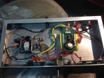
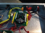
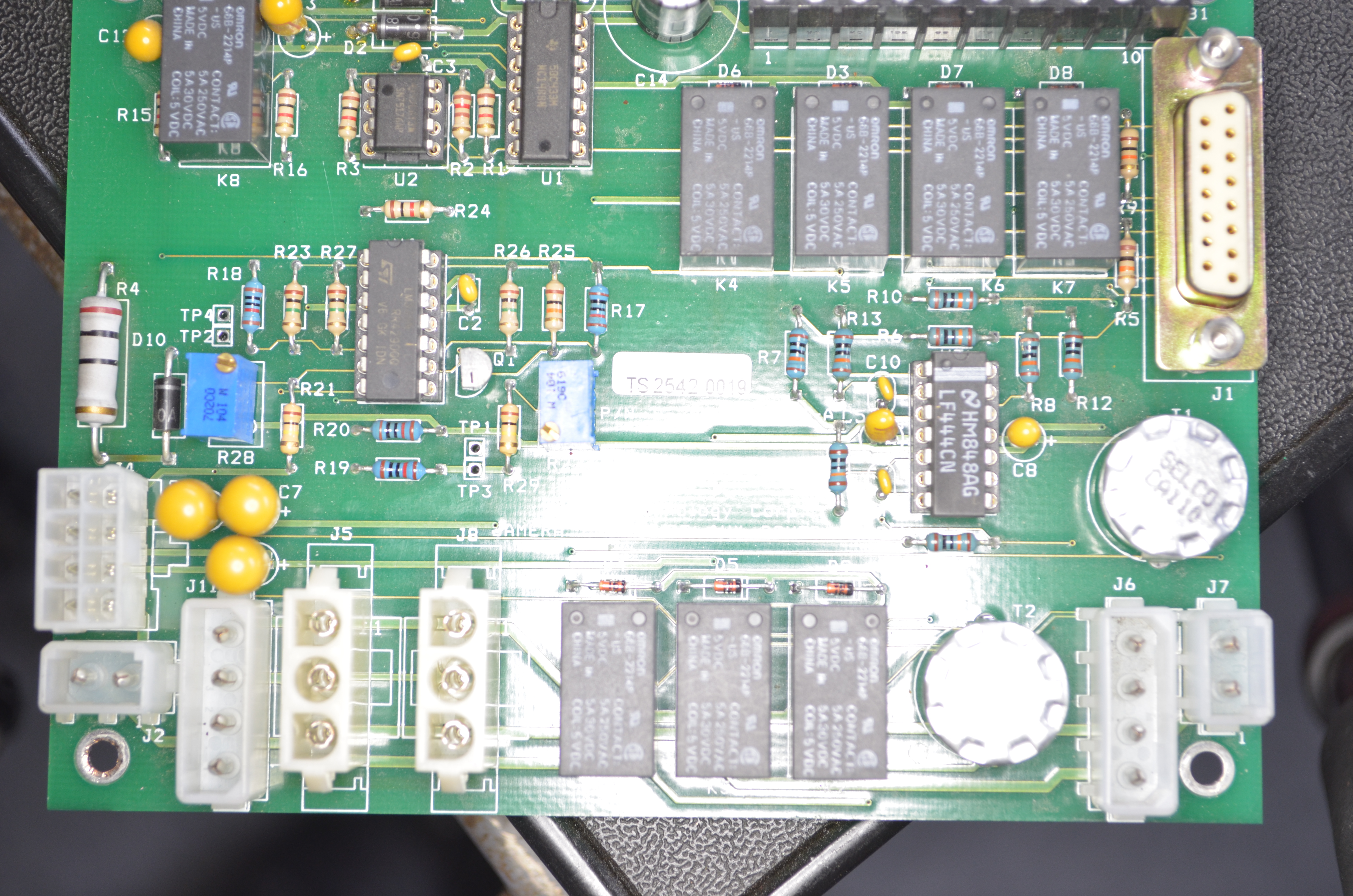
So we were given a Troll Systems camera housing with everything except the S750 master controller. Instead of spending thousands of dollars on a master controller, we’re going to break out the connector and control the camera ourselves. Here are the pics of the circuit board and a diagram of the pinouts.

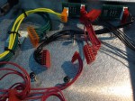
Here is the pinout of the Hirose 10P 12 Pin connector that is on the Canon YJ20x8.5B4 KTS PX12 / BCTV Zoom Lens:
 Here is the Hirose 10P Male connector pin chart, I have verified the correct position of the ground pin with the table above. The female end is on the lens, and the male end comes from the camera housing circuit board.

So after some probing, checking and double checking, here is how the Hirose connector breaks out onto the 7 pin connector on the circuit board:
| Pin# | Wire Color | Function | Hirose 10P Pin# |
|---|---|---|---|
| 1 | Brown | Focus Mode | 1 |
| 2 | Orange | Zoom Mode | 2 |
| 3 | Yellow | Power +12V | 6 |
| 4 | Green | Iris Mode | 10 |
| 5 | Blue | Focus Control | 8 |
| 6 | Red | Zoom Control | 9 |
| 7 | Black | Ground | 3 |


Here are the high resolution images of the board provided by Editor:


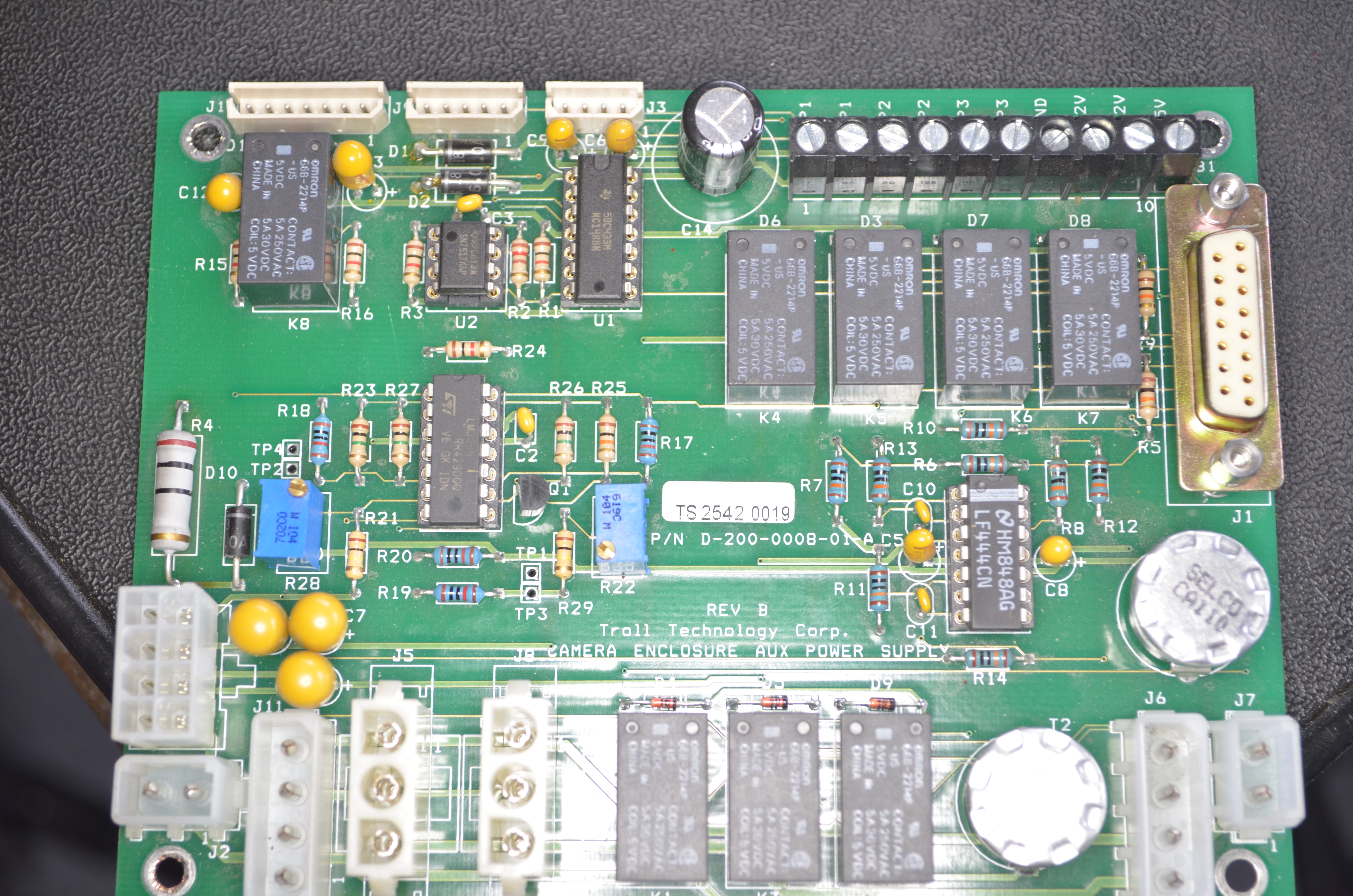

Thanks to IRC members oPossum, TreeHouseMan, Monkeh, Rakky, Kire, Erlend and a few others you can download the reverse engineered schematic by clicking here. You will need the free software from ExpressPCB to open it, which you can find here: http://expresspcb.com/ Since we are not designing a new circuit board but merely laying out a schematic, ExpressSCH is the quick and dirty way to our endgoal. Once I design a new board to control this one, that will be done in Eagle.
Here is the pinouts of the DB15 connector to the big circular connector:
| DB15 Pin / Wire Color | Big Connector / Wire Color | Function |
|---|---|---|
| 1 / Yellow-Black | R / Orange-Black | Serial TX+ |
| 2 / Green-Black | S / Brown-Black | Serial TX- |
| 3 / Yellow-White | Z / Blue Wire | Washer on/off |
| 4 / Orange | X / Red-Black | Camera Power on |
| 5 / Not Connected | ||
| 6 / Green-White | a / Red-White | Heater On / Fan On |
| 7 / Brown-Black | M / Red | Analog Focus |
| 8 / Red-Black | N / Grey | Analog Zoom |
| 9 / Brown-White | W / | Wiper |
| 10 / Red-White | Y / | Fan On / Off |
| 11 / Purple-White | d / | Spare Analog In |
| 12 / Orange-Black | P / Orange | Analog iris |
| 13 / Green-White | J / Black-Red | Reference Ground |
| 14 / Black | A / Black | Ground |
| 15 / Black | A / Black | Ground |
Here is another shot of some of the schematic:

Theory of operation:
As far as the fan, heater, washer / wiper controls are concerned. Those pins just get grounded to turn on the associated relay for that feature.
Thanks to reverse engineering we’ve figured out how the board exactly operates. Both the Focus and Zoom controls must fall within a certain voltage range before remote control is enabled. Once they are both in range relay K8 activates to release remote control.
Trim pot R28 adjusts the low voltage threshold to enable remote control, R22 is the high voltage cutoff, if the voltage is exceeded beyond the limit set by R22 remote control is disabled again. You can probe across TP1 and TP3 while adjusting to measure the voltage, multiply by 2 for your input voltage. TP2 and TP4 are the test points to measure the low voltage cut off.
——————————————————————
I have plans to use a PIC1F628, with an MCP4822 and an op-amp to drive the lens control stuff.
Some manuals / other links that are good for reference:
S750 Setup: http://www.mafware.com/writing-samples/mrc/CRS-Install-Guide.pdf
Camera that we have in the housing: http://www.hitachi-keu.com/content/industry/kameras_3ccd/pdf/hv-d15.pdf
Serial Protocol details for the Hitachi Camera: http://www.hitachikokusai.com/idc/groups/hitachikokusai/documents/supportingdocumentpdf/poc_007435.pdf
Creating a new controller:
We are starting with a 1U enclosure that was previously a camera controller of a different sort. This will be the enclosure that we will be starting with in creating a new controller: