
WHEN SERVICING THE EG33 / SVX ENGINE!
Always remember that the intake manifold comes off the engine as one piece. You can separate the two as you take it apart but you will hate yourself and bend and break a lot of vacuum lines. I actually ended up breaking one of the EGR solenoids but that is okay because I am removing all that stuff anyways. Just remove the bolts that secure the lower of the two pieces and then you will only need to disconnect a small amount of vacuum lines.

For the initial assembly I actually made a set of intake manifold gaskets, as they are a dealership only part that had been on back order for while. I ordered a whole host of replacement seals and gaskets and these were the only ones that the dealership couldn’t obtain (at $50 each I might add) so I decided to just make a set. At the time of the writing, 8,200 miles in, it is holding great:


Sticking it all together:
Now that I had a good solid engine to start with it was time to figure out how to go about stuffing it into the Vanagon’s engine compartment. First order of business was to figure out how to adapt the Subaru engine to the factory VW trans-axle. I researched several options and soon came across an interesting solution, the smallcar bellhousing.
There was much debate about whether to use the bell-housing or go with an adapter plate kit. The bell-housing was more expensive but being able to use the Subaru flywheel and starter were important to me because I know these items will be readily and cheaply available for years to come. There were some other benefits that lead to ultimately to the purchase:
– Increases distance between the front of crankshaft pulley and the back of the engine compartment.
– Was said to reduce drive-train vibration compared to the adapter plate kits
– Will accept the bolt pattern for 06+ Subaru engines as well, for example the EZ36
– Cleaner installation look overall
So I placed my order with smallcar completely unsure of what to expect, this was my first major cash investment into this project at nice lump sum of $700, not including the $350 for the clutch. I considered that a huge investment at the time because the total cost of the project up until the point (so van and Subaru swap car) had only been about $100. About a week later this showed up:

Clutch slave and associated bell-housing hardware, note how the slave cylinder is the “ford” style:


I wasted no time getting started on affixing it to the transmission. The installation documentation on this was thorough and easily understood. Providing you only have a 2WD Vanagon the bell-housing requires no specialty tools for installation. This allowed me to get a better look inside my junkyard purchased transmission:

After cleaning everything very nicely it was time to install the main-shaft extension. This is a little bit of a reach with the diff in the way:

One installation note that I recommend that isn’t in the docs is that the o-ring for the clutch slave cylinder really needs to be greased up before insertion, remember to take extra special care to not tear the o-ring on the non contersync’d surface. (the hole doesn’t taper in) After pulling the threads torquing one of the clutch slave bolts to spec and re-tapping for the next size up bolt I finally had an assembled transmission:


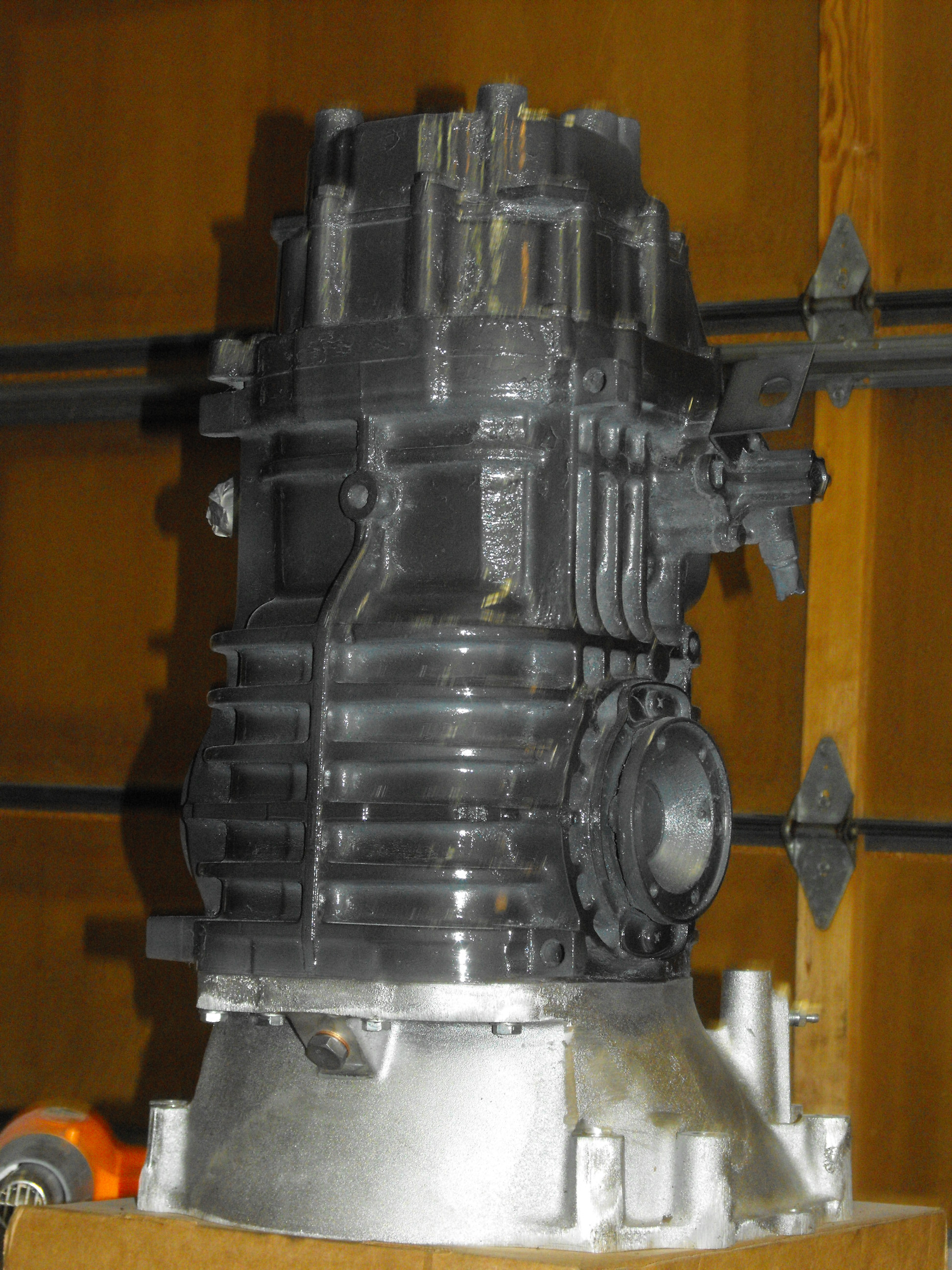
The next step was to check initial fitment to the engine, the clutch kit hadn’t actually arrived yet but it’s huge from a motivational standpoint to see it stuck together:


Note the down-pipe would never work for this setup but it would be cool! This is actually the turbocharger I plan on using with Albert but it’s not going there:

Time for paint I think things fit and finished:


Looks good smoked:
With the transmission squared away it was time to address the clutch kit, instead of ordering your Subaru flywheel online just go to the auto parts store, I paid a measly $75 for a brand new flywheel:


This clutch kit is a “Stage II”:

Stuffing it all into the engine bay:
Having never personally seen a SVX Vanagon it was quite a day when I decided to test fit the whole swap in Albert for the first time. The first time I went to shove the lump under I realized how much of a chore it was, having never actually installed an engine “Fiero” or “MR-2″ style before meant more uncharted territory. The lowest hanging part of the vanagon will need to be a minimum of 25 – 26” off the ground in order to clear the SVX Engine’s throttle body which is the highest point on the engine swap.

I used an old “stop sign pole” as a cross brace to suspend the engine swap from, in this picture the engine is suspended here and the transmission mount has been bolted up:

I used a jack underneath to level the engine in the bay:

Next up was to get the engine secured in the engine bay the rest of the way, now because the EG33 has two extra cylinders on it the stock VW rear cross member must be moved to accommodate the larger size. When holding up the VW cross member to the potentially new location a major issue became evident, the frame rails narrow slightly as they get closer to the rear. This caused the holes for the cross member to be wider than the frame was at the rear, and after some brainstorming came up with a solution. I took two pieces of angle iron and notched one side for the bumper bolts and drilled holes in the other side for the cross member to actually bolt to. I also added another set of bolts that hold the cross member to the van, bringing the total up to 6. I am not really confident in how this will handle 300hp so when I start on turbocharging project I may fabricate an entirely new, beefier cross-member and anchor points at the same time. First I bolted up the EG33 side of the engine mount hardware and attached 2 of the 5 rubber mounts to hold the cross member up for alignment:


Here are the holes where the bumper bolts go through, prepare to spend some time drilling. I actually had a drill press I was able to reverse the drill direction of so I could drill upwards:

The notched angle iron:

When setting up to mark your new cross-member holes remember to take your time! You will need to measure everything and make it as center as possible, also be sure that your cross member is facing the correct direction and is not pre-loading the mounts in any funny directions. I spent about 30 minutes taking measurements and making adjustments before I finally locked in on a good location:

This gave me a first realistic look at the ground clearence for the oil pan, this was a noted concern that was brought up when scouring the internet but really on the 2WD it’s not as bad as I was expecting:

Sitting in the bay for the first time without help:
Looking from the side:

Removing and installing an SVX swap DoogieStyle:
After initially shoving everything under with just a tire I was quickly annoyed and tired with the whole process, and since I couldn’t just wheel it under with an engine hoist a more viable option had to be found. After looking at an old shopping cart I had it hit me, make an engine cart!
Actually if you have a shopping cart this is the easiest thing in the world to make, all you need is a cutoff wheel or a sawzall. Basically you cut the cart part off the top of the wheel platform, cutting as close as you can to the frame to provide as smooth of a surface as possible. Then you’ll want to remove the lower shelf and by the end you should be left with 4 wheels and the frame they bolt into. There should be no type of cross bracing other than at the front where the front wheels mount. This becomes your engine cart, the only thing you will need to do from this point is take some rags and a roll of duct tape and pad where you had cut the cart top off (at the back wheels of the shopping cart). Wrap each “leg” so that the rag or tape doesn’t interfere with wheel operation but padded enough to acceptably contact a gasket surface.
When you goto put the engine / trans on the cart the two will need to be bolted together already, and the whole lot suspended from an engine hoist. Next you wheel the cart underneath so that the front of the shopping cart sits underneath the transmission about where the shifter mechanism is located. This is where the “front cross-brace and wheels” of the cart will sit underneath. Next looking at the “legs” (each leg should have a wheel so 2 legs) that you padded earlier you will notice that they almost line up with the exhaust manifold gasket surfaces. In fact, the cart legs should be a little wider than the two surfaces but that is okay because it’s flexible! You will want to position one leg in between the studs for the exhaust manifold and then while holding that up with one hand take your other hand and pull the other leg inwards and into the studs on the opposing exhaust manifold gasket surface. Each leg should be in-between the rows of studs and covering the exhaust ports of the engine, at this point you can lower your engine and trans assy onto the cart and let the cart take the full weight of both. You will find the “tension” of pulling that leg in very handy as it will stabilize the engine and allow the front of the engine to rest on only the two wheels while the other end is jacked up to connect the transmission mount:

This cart allows many huge conveniences, the first being that you can fully assemble your engine swap, cross member and mounts(minus exhaust)and freely wheel it around the floor and under your van for installation:

The second being that with the stock oil pan it really does give me the exact ground clearance I need to wheel it under the Vanagon, all without modification, NICE!

Here it is ready to be stuffed, since I have started using this cart it has cut engine removal time down to 40 minutes, and installation time to a little over a hour.

Rolls right under, then all you do is bolt up the trans mount and lift the engine in using a hoist or jacks from underneath to attack the cross-member bolts, I actually plan on adding more information about this cart and a step by step engine installation process when the JDM engine installation takes place::

A moment in reflection of a job well done:

One of the initial things you’ll notice in a Vanagon is how the engine compartment is divided by some sheet metal, You are going to need to cut this out to allow clearance of the air intake box, I ended up starting by leaving about 1.5″ of metal from the outside edge of the drivers Side electrical box. Cut upwards until you get to the cross Support for the Floor which is only about an in or So thick. Next you start your cross cut and really you only need to go a couple of inches past the airbox, but I continued past even the coolant lines because on a 2WD Vanagon using the smallcar Stainless lines they need you to shorten the pipes about 6″. I didn’t seem to take any pictures of this and I am un-sure why, however when the engine is out the next time for the JDM Engine Installation I will take some pictures of the engine compartment cutout so everyone has a better understanding.
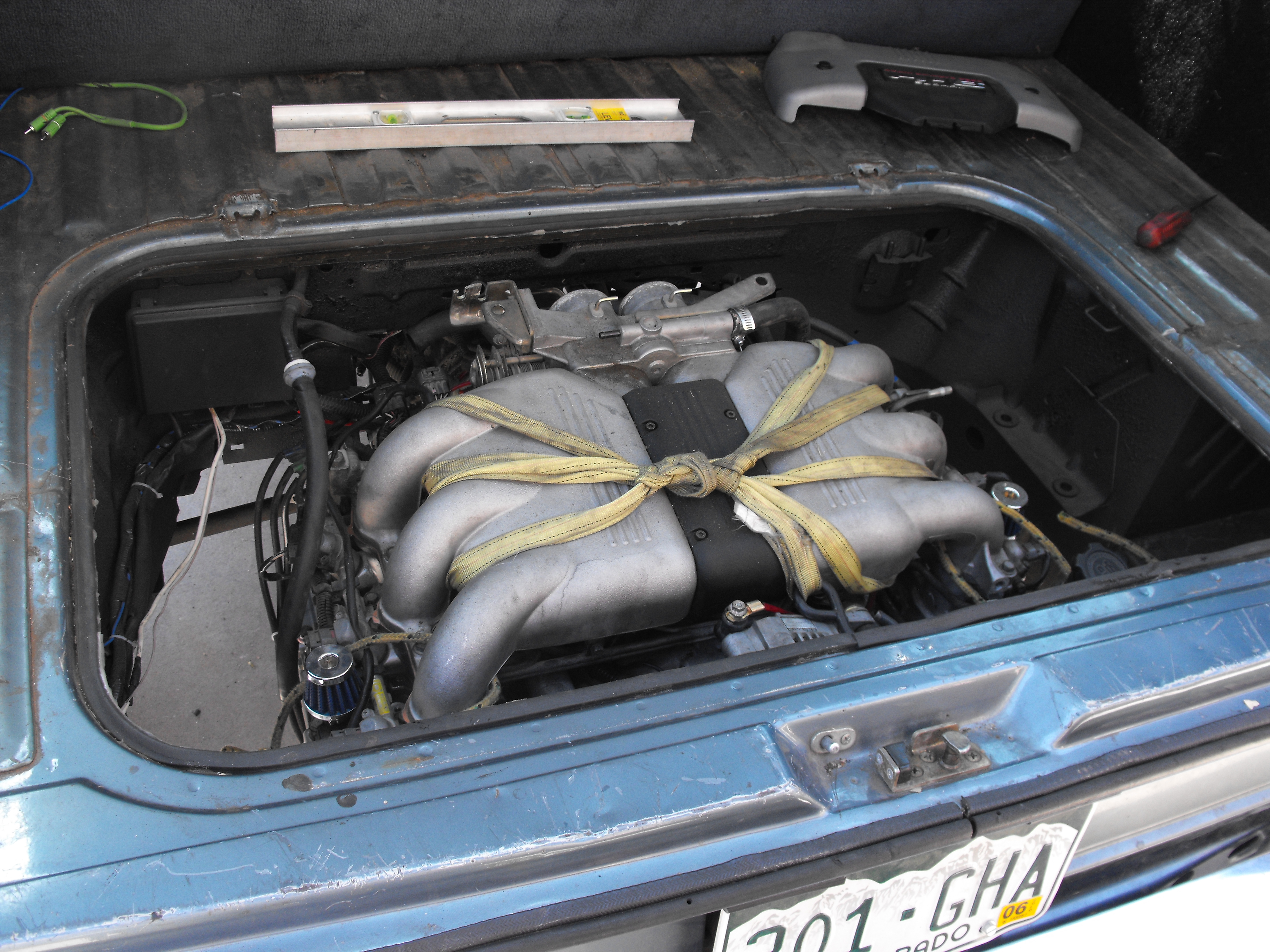
One thing you’ll most definitely notice is when using the smallcar mount kit it makes the engine sit really high in the engine bay, it really does fit perfect with the exception of the snazzy name plate that sits on top of the throttle body as you can see you can’t shut the engine compartment cover anyways:

It took about 10 minutes of brainstorming before I came up with a good idea, I never liked the huge plastic part that went around everything anyways so I just decided to cut it out:

In these next two pictures you can get a general idea on how I cut the divider out in the engine bay, you can see how I went a little wider to include the coolant lines:


New cutout name badge installed, this actually still rubs on the bottom of the engine cover but luckily that is all foam so it doesn’t scratch the letters on top:

After doing some of the trans stuff (axles, shifter, etc) it was time for the initial air filter installation. I actually create a cold air intake setup for this bad boy on the performance section of the vanagon page. (here)

I like stuff that matches colors:


This project didn’t go without it’s share of problems and this was one of the most irritating ones to date, there apparently was a batch of bell-housings that were machined slightly out of spec causing the clutch slave cylinder to leak. The initial fix for this was to install a second O-ring which seemed to do the trick for me, but it wasn’t much fun taking things back apart. Since I have put 9,000 miles on the swap I haven’t seen anymore issues and will post some inspection pictures once it all comes back apart:

New one piece speedo cable to get rid of that O2 sensor box:

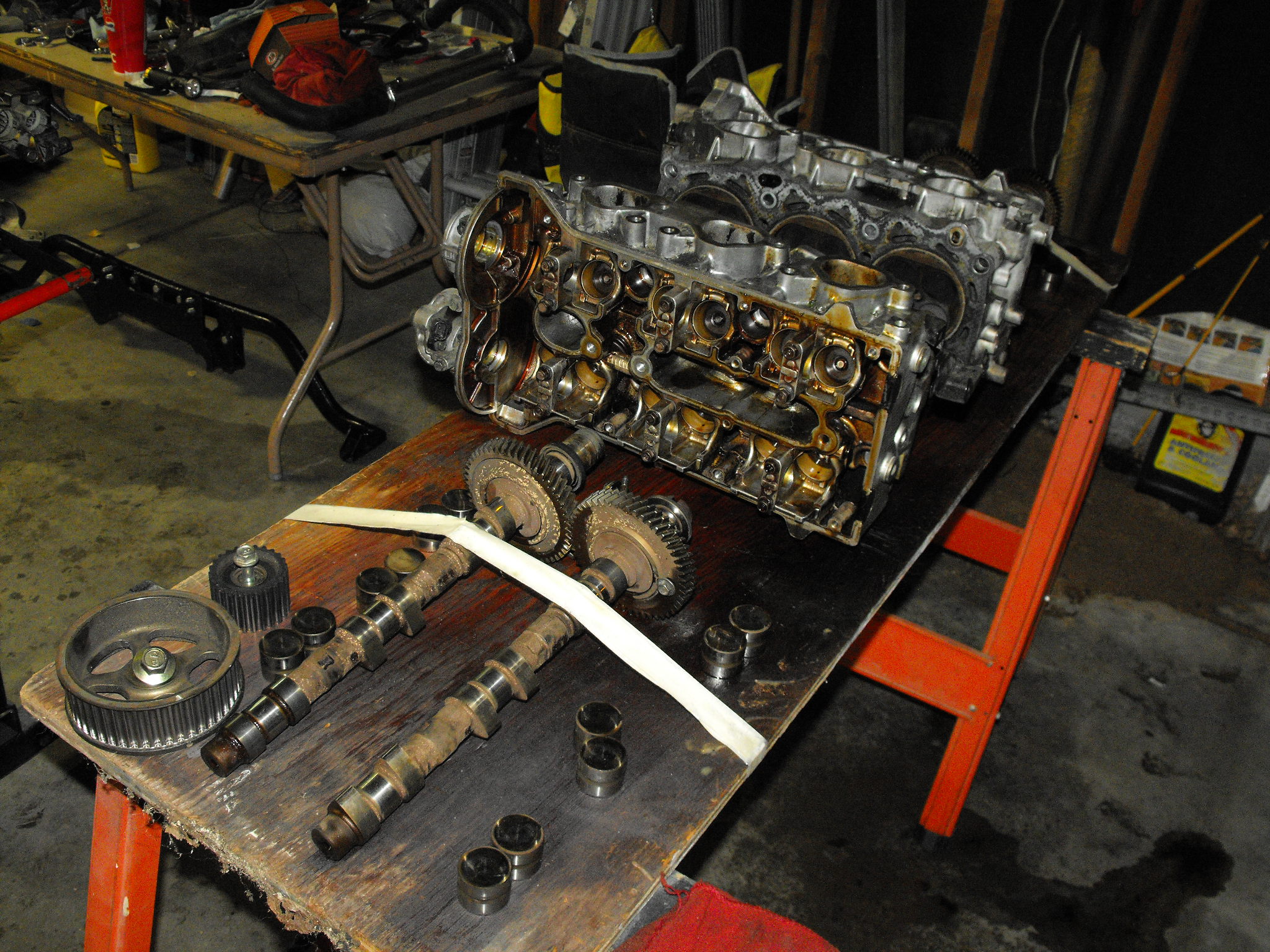
Replacing an EG33 Head-gasket:
The second major issue with this project; After getting the engine installed and wired and actually driving Albert for the first time a problem soon arose. Once the engine was warm it would start to misfire on one hole and start spitting out white smoke which was a tell-tale sign that the head-gasket was gone. The head-gaskets are known to be weaksauce on Subaru engines and with the EG33 being a close cousin of the EJ22 this meant there was no exception. The thing that really irritated me with this engine was the evidence that it had been driven for quite sometime that state of disrepair. For example, the thermostat had been gutted. The most likely reason for this is to prevent the car from overheating which would most certainly happen with a head-gasket blow-out of this type. It was because of this fact I ultimately decided to purchase a second, JDM engine, but in the meantime this needed to be addressed so lets start tearing into it:

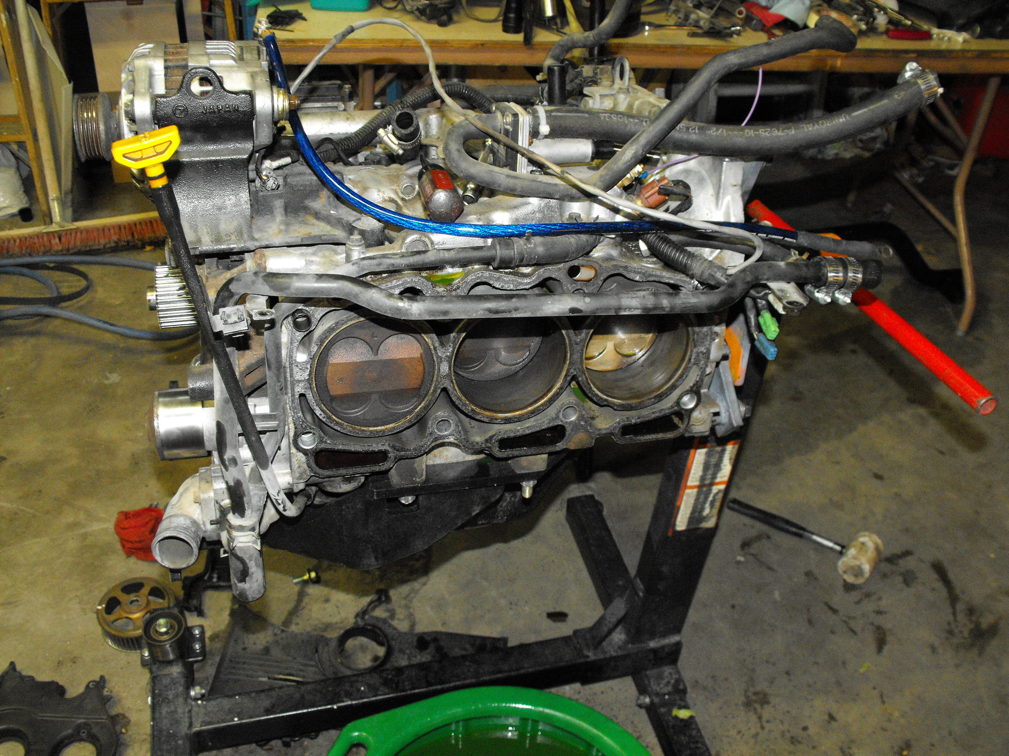
It was quite nice to be able to get acquainted with the EG33 in this manner, I feel much more comfortable with Subaru engines now as a result. Here is the side that had the blown gasket:
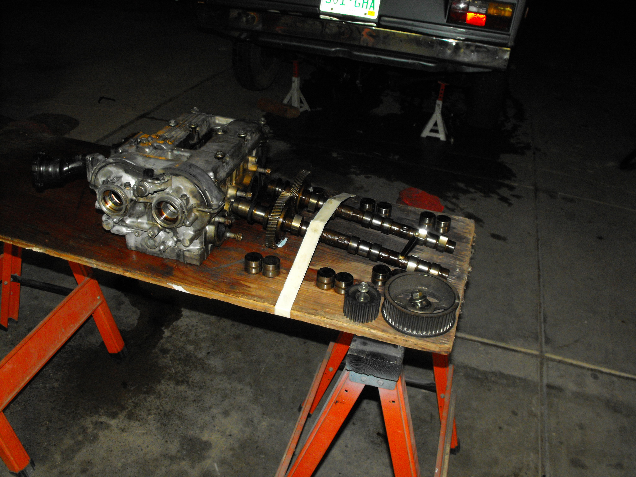
Good organization means everything will go back exactly the way it was:
I love how small the actual block is in itself:

Even though this is the opposing side this picture is a great time to explain how the gasket actually failed. There are bolts at the very bottom of the water jackets that hold the two halves of the engine block together, these bolts are close to the sleeves and as a result the sleeve requires a notch cut it in it to allow clearance of the socket and extension. These notches pictured on the rearmost cylinder below are the weak points that cause most head-gasket failures in these engines. Subaru actually re-designed them with a metal gasket but superseded the part number several years ago with the felpro style material which is the very same gasket that failed in the motor from the factory, which meant for me that this was the only gasket I could get from the dealer so it’s what I installed into this engine. HOWEVER! Cometic gaskets will make them to order for you and they are the metal ones! I will most certainly be purchasing a set for the JDM engine because multi-layer steel gaskets is the only thing I am comfortable with running in my engines. It’s really worth the peace of mind!

Here is a link to cometic’s site: http://www.cometic.com/sportcompact.aspx and here is a little snippet of about what to expect to pay for them (per side):

Both sides ready to be cleaned:


The parts look interesting when they have been washed and dried:
Just another engine shot:

After cleaning the head-gasket surface and checking for straightness, I also cleaned the forged aluminum piston tops, they just beg for boost! You can also see those notches better that are on the outside of the sleeves, the notch at 7 o’ clock on the right most cylinder pictured below is where the head-gasket failure occurred on this particular engine:

Wheeled the block outside for it’s cleaning. It’s kind of fascinating when you receive an engine with 20 years of crap wedged in between the intake manifold and the top of the block. I found leaves, pieces of newspaper, an extremely old paper towel, pine needles, and a whole heap of grease. It’s a great example of what happens when you never wash off your engine, which is something I include in my routine maintenance:

The new (non metal grrrr) head-gasket copper sprayed and ready to make that ever important seal:

After the heads are torqued the rest of the assembly goes fairly quickly:

However, because of the attention to detail I was paying toward assembly I didn’t stop for pictures until it was ready to go back in:

Exhaust:
There were a couple of weeks I ran around on the stock exhaust manifolds, if you have looked at the stock manifolds you will notice they are reversible so you can make the outlets face rearwards. The problem however is that there isn’t enough distance between the outlet of the manifold and the back of the vehicle to be able to squeeze a muffler in, as well as ground clearance issues.
The solution? a $450 piece from smallcar that is a conversion header for your SVX swapped Vanagon. It’s stainless and it looks pretty:

Don’t let the shininess fool you.. This baby sits below, and behind everything so unless you take it off every oil change and polish it this is the last time you’ll see it this nice:

It’s nice to look under and see a stainless piece it dresses up the whole engine bay:

I really like how the outlet is set far enough forward that you have a few exhaust system options:

Using my harbor freight el-cheapo welder I was able to fab an exhaust. It was recommended to me to try purchasing a flow-master muffler but unless you want something along the lines of loud and annoying I don’t recommend wasting the $70+ for it. I ended up switching to a muffler from Vibrant Performance that we had laying around for the other Corrado. This is my exhaust when it was the Flowmaster:
8500 Mile Update:
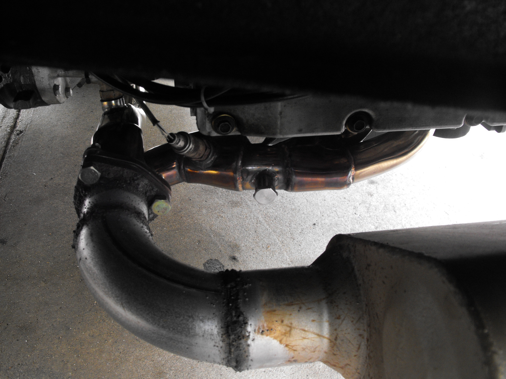
This header cracked on me shortly after installation. I would say about 4,000 – 6,000 miles in the first crack / exhaust leak developed. Since I didn’t have an arc welder I had to source locally a place to repair the damages. Smallcar offered to fix the cracks free of charge but I would have the eat the cost of shipping as well as have the van out of commission for a couple of weeks, not good. I actually got lucky enough to call in a favor to one of my buddies and he did an exceptional job. He actually not only works with stainless but regularly fabricates titanium headers and the like. He is the 2nd best welder I have seen (next to a woman!)His many years of expertise proved key in a failure analysis of this header so here we go.
First after removing the header for repairs a quick inspection of the gaskets reveals some telltale signs of the exhaust leaks:
This type of failure occurred because the flanges were not surfaced after the welding process in manufacturing, measuring with a straight edge confirms this:
Each side cracked at the same joint, one side the crack wraps around more than 3/4 of the circumference:
Driver’s side:
Here are the patches that he had made, he first cleaned and welded the crack itself and then applied a patch because he indicated to me that only welding it will most certainly cause it to crack again. He commented about how the walls of the header were thin and used the lowest power setting on his welder (which it was grumpy about). In his professional opinion the header only cracked because the welds weren’t gas purged. (pressurizing the inside of the tube with a gas during the welding process, which is the methodology he used for making the repairs)
We did find a third crack starting and only welded it as it was only about 1/4″ long, him and I agree that the header will continue to crack at various stress points so if you have purchased a similar header, BE PREPARED!


The Vibrant performance muffler (Take your pick here) was what I eventually switched to, it’s a straight through design that provides a rich, deep exhaust tone. There is still a little rasp but I plan on rectifying that situation by using an exhaust tip that contains a built in resonator. This muffler was twice as quiet as the flow-master and also looks much more appealing.
It’s all covered in water spots but you get the general idea:
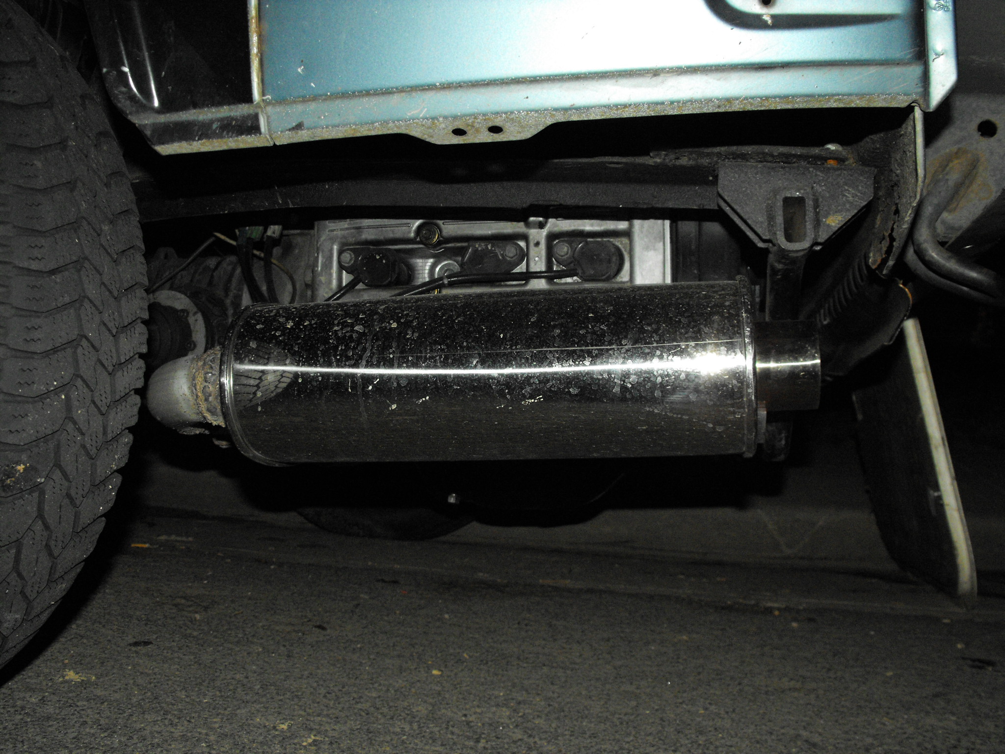
For those wondering about the cut out above the exhaust outlet it was for rust removal:

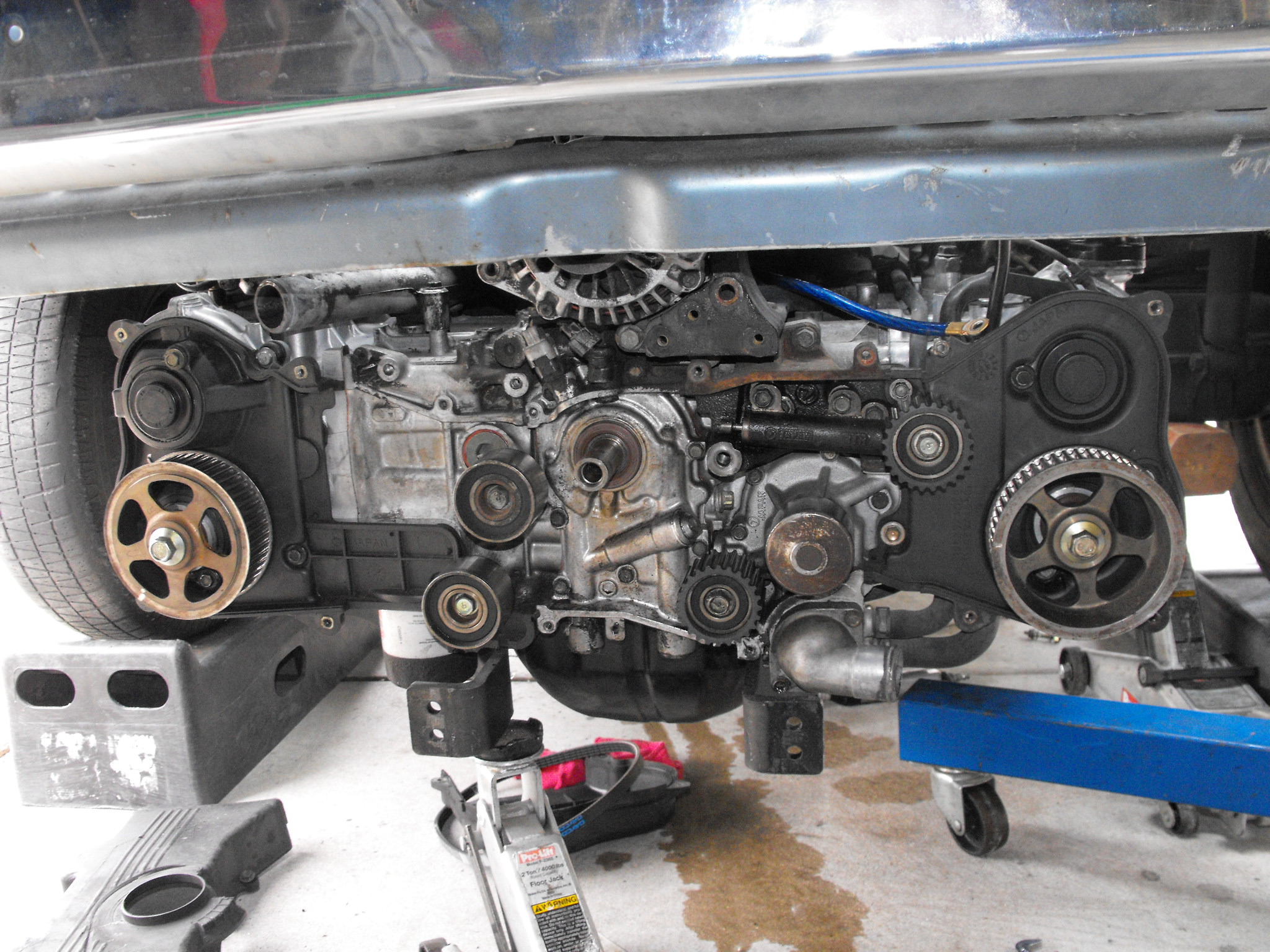
After getting the exhaust squared away it was time to tie up the final loose ends. First off, if you are considering for any reason leaving the original seals in your swap engine DON’T! I replaced everything except the front main and guess what started leaking. Doing stuff like this isn’t all that complicated in the Vanagon because really the SVX engine remains just as easily accessible as the stock VW engine was, it only took about 30 minutes to complete:
Cooling System:
The next thing was the cooling system. Actually, up until this point I ran a home-made set of hoses using a culmination of stock Vanagon and Corrado parts and it worked OK. The cooling system I made was temporary as smallcar makes a nice “cooling system conversion kit” which includes stainless steel lines so I had to have it. This is the diagram I used as a reference when creating my cooling system, note the “reversed” coolant manifold is a service that smallcar can perform to move the water outlet to the passenger side rear corner of the engine. (or front of engine bay however you want to look at it.)

I recommend the smallcar kit because it makes bleeding the cooling system almost as effortless as if it were a front engined / FWD sedan. Their kit utilizes the 86 and up Vanagon cooling bottle and all the pipes are designed to trap the air bubbles in the bottle. Here is everything laid out on the floor:


Actual fitment of the pieces is OK. Remember that this kit is actually made to fit all the Subaru swaps and naturally seems like it fits the 4 cylinder swaps slightly better. Remember to take your time and really play with the lengths of tubing to assure good free-flowing operation.

The cooling system works remarkably well, I still have not replaced the thermostat since I have discovered that was MIA, however letting the engine warm up it never goes past 180F and even if gets up there once you start moving it will dip well below if it’s chilly outside at all. Expect around 150F water temps on a 60F day, 180-190 range on a 90+F day,and if you have no thermostat it won’t warm up in the winter time. HOWEVER I did experience some minor leaks, the cause of this was determined to be the hoseclamps weren’t beefy enough to deal with the extra thickness of the heavier duty hose. Even later on the regular thickness hose started to leak so I doubled up on every main line hoseclamp, and I haven’t had any leaks since.

Positioning the 86+ coolant bottle:

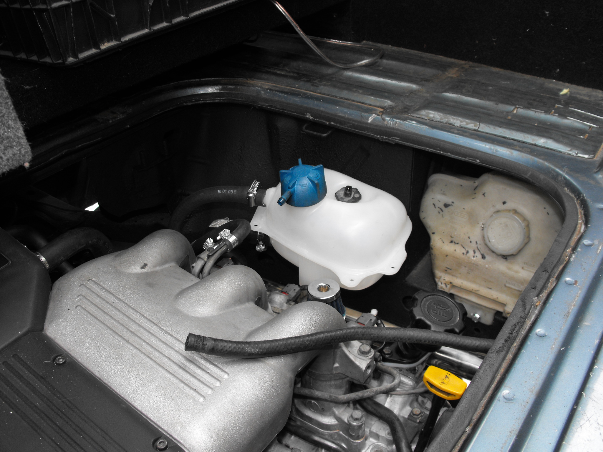

Here is the bracket for the coolant bottle, this is a part of the smallcar cooling conversion kit and they forgot to send me this piece but a short time later it did arrive. As with most of all aftermarket pieces fitment of stuff is never 100% correct. I can think of countless examples I have had to modify an aftermarket for it to properly fit it’s intended application. This proved to be no exception as I ended up cutting some notches for the “supports” of the bracket it bolts onto:

The final cooling system, note the overflow has been moved to the passenger side scoop-box, for personal preference, because it won’t fit behind the license plate. (the alternator goes there)

This concludes the initial engine installation, minus wiring but all of those details are found under the electrical section. Everything done up to this point is what any typical svx conversion will take, this was easier than most because my 84 doesn’t have power steering and the a/c was damaged beyond repair so that stuff was removed. There are other things you can do with an a/c pump including an on-board air system. (train horns, and for air tools of course!) If you have any questions please let me know, I intend on updating the pages with good / common questions and answers so don’t hesitate.