Hello everyone! Quite a bit has happened since I posted here last, so lets take it from the top.
Albert has been doing great since the timing belt break. I have driven a few hundred more miles and things are sound, other than it’s pig rich. It will be another couple of weeks before I am able to afford the needed Dyno time to finish sorting things out tuning wise. Even with the enormous amounts of fuel it still goes like it means business. The transmission feels much better after getting over 1,000 miles on it, and I am seeing around 16mpg.
Every once in a while I end up messing around with stuff and Albert does pretty good, all that torque really helps! Here is a video taken by a Friday night cruiser:
I have started writing the code for my PIC16f Micro-controller to interface with the Subaru Select monitor port provided by the SVX ecu. I actually am a bit stuck on whether or not I am properly receiving data, as well as how to decipher it. It will take many more hours of understanding and experimenting. I am sure at this point I have the baud parameters set correctly in the controller (1953, 8E1) and have been displaying data inputted in various formats in an attempt to understand what the ECU is sending. Here is the setup in the Van I have been using for my electronics research, the summer heat has been tempting me to go into a junkyard and cut the ECU harness out of an SVX to make a test bench. I just may do that!
This is a closeup of the prototyped pic circuit, this is a temporary circuit created only with the goal in mind to establish communications. Once a working solution is found I can move forward with creation of the main controller for the instrument cluster, this circuit consists of a PIC16F648, a MAX232 for PC serial comms and a 10K pulldown resistor tied into the ECU signal wires that are connected to the PIC’s USART:
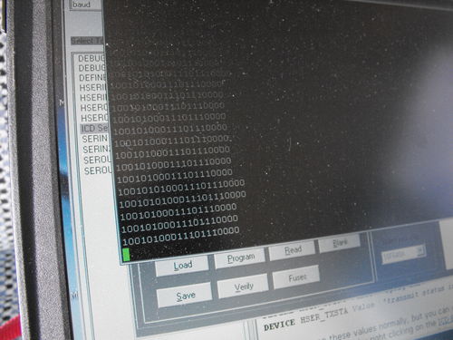
The next photo shows the ECU reading back data to the PIC which displays it in a 9600 8N1 terminal. I have chosen the binary format. To get the ECU to generate output I connected to the Select Monitor port using the RS232 hex com tool and issued the “78123400” test command, the ECU replies back 123400 repeatedly, infinitely until you tell it to stop. So somewhere in this binary is the hex 123400, repeating over and over:
Once my code can successfully navigate the SSM that will be a gigantic step forward. Since the basic display driver is already done this is technically a final piece to the puzzle for me to build a test cluster. I am going to research the use of a couple other components I would like to integrate into the circuit before building my first full cluster, such as the use of a frame buffer.
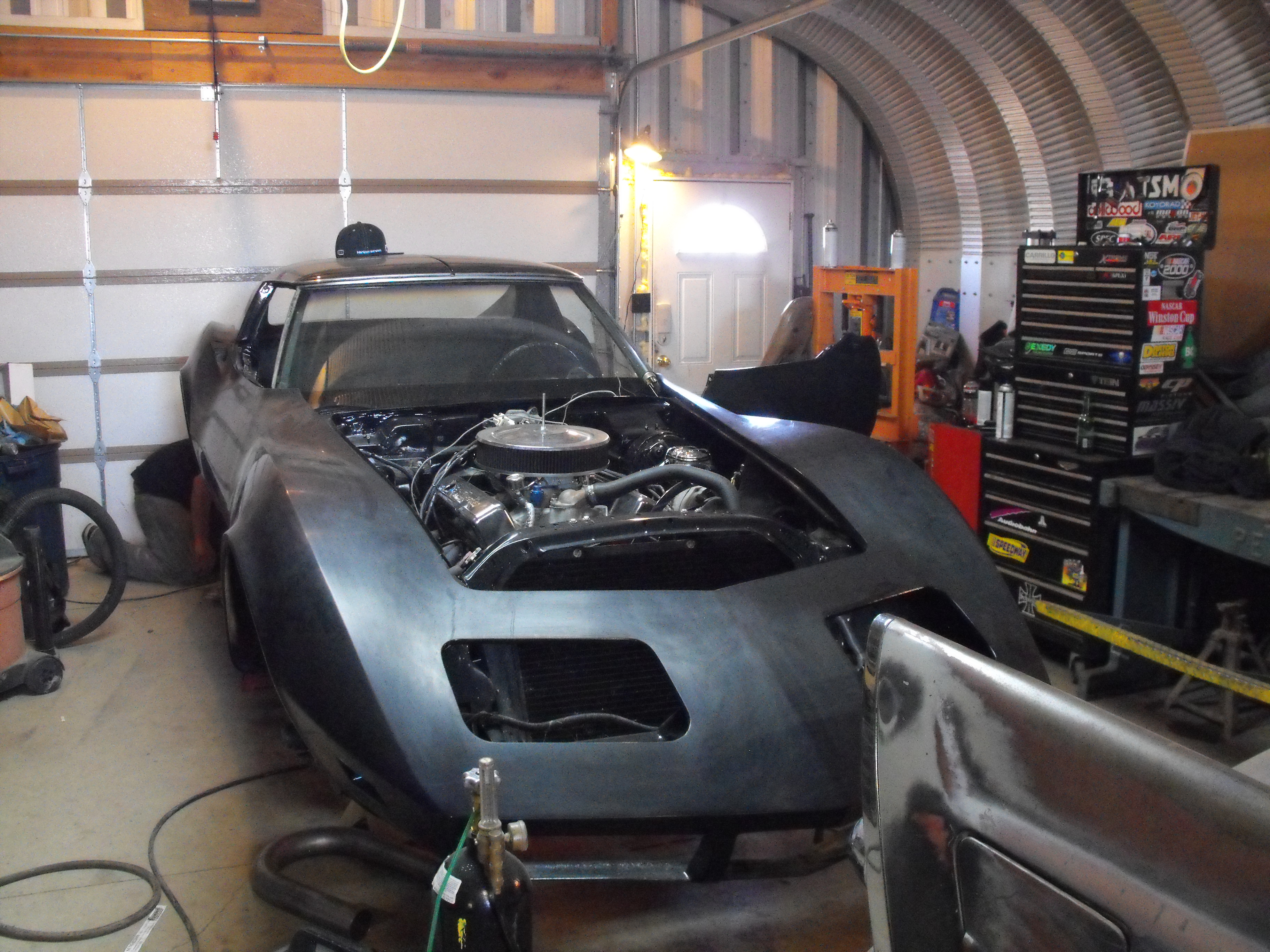
As far as other stuff I have completed on the Van I received and installed my new bumpers! This once again completely changed the look of Albert. I also got an exhaust tip with a built in resonator which makes for the final needed piece to keep the exhaust quiet:
EG33 Failure Analysis update:
I finally was able to get the 14mm Allen I needed to get to the plugs that access the wrist pins allowing me to disassemble the block the rest of the way. For those who aren’t familiar with an EG33, or other Subaru engines in order to get the crankshaft / rods out you need to split the block into two pieces as these items are sandwiched in the middle. The webbing in the block doesn’t allow enough proper access to get a ratchet in there to the rod bolts, so you remove the wrist pin of the piston and pop the piston out first, then you can split the block. There are some writeups and videos online about the assembly of an EG33 but nothing really covers disassembly in detail, here is the easiest and fastest way to disassemble an EG33 block:
After removing the heads, water pump, all brackets and water pipes there will be two plugs on the front of the block similar to this, the ones on the flywheel side are located behind a large panel on the passengers side of the engine secured by Phillips screws, and another diamond shaped plug also secured by Phillips screws:
Remove this plug, you will only need to remove the plugs on the front and back on one side of the engine. My trick involves leaving 3 Pistons / Rods in the block until after its split. After the plug is removed and the closest piston is set to bottom dead center the wrist pin and clip should come into view:
Alternative angle:
There is one of these clips on each end of the wristpin. You will only need to remove the one closest to the hole you want the pin to pop out of. Once the pin is removed look in the hole at the opposite end of the block, you’ll notice that the other 2 cylinders in the row are positioned in such a way you can actually reach a long rod all the way through to the pin you have set at BDC. I used three 12″ Long 1/4″ Drive extensions chained together with a hammer, fished them in from the backside while looking through the hole in the front to make sure I am against the pin and not the tabs of the clip that stick down. If you find that your clip tabs are at the bottom and gravity isn’t helping you much you can stick a large flat blade in through the hole and actually rotate the clip so the tabs are out of the way. Once positioned you can pound the wrist pin out of it’s hole, use extra caution and common sense where necessary to avoid damage to the piston, pin, cylinder walls, etc.
After the pin is pounded out take your 1/4″ Drive contraption and fish in up through the block webbing into the bottom of the piston, and gently push the piston out of the cylinder. Repeat this process for the two remaining cylinders in the row, leaving the other side completely untouched, then proceed to split the block. In this photo cylinders 1, 3, and 5 were removed using the above outlined procedure and 2, 4, and 6 remained installed:
Finally inside the mighty EG33 showing all 7 mains:
Here is a video that covers the EG33’s reassembly, in particular installation of the middle wrist pin:
After all of that what did I find out? Lots actually, the main failure of the engine was caused from detonation, It could have been caused by a lean condition, or too much timing. The software that was run on this isn’t wasn’t of my custom modification, instead it was the ECU Tune Stage I software. I seriously doubt that caused any of this to the engine, actually I believe it was a combination of fuel starvation and previous owner abuse.
After first installing this Craigslist swap motor I did notice a slight noise between 2000 – 2500, if you held the engine somewhere within that rpm range right around 22-2300 I would hear what can be considered a “sloppy bottom end” it wasn’t any type of knock, but everything was just sloppy. It sounded like a wrist pin noise kind of does on the VW 8 Valve motors, so even at the time I had some suspicions that something was a miss, but then I dismissed it as the wrist pin noise it similarly sounded like. I was wrong, it was the rod bearings. The old knock sensors were both cracked, I suspect the P.O. used 85 octane, or the lowest grade gas possible when driving this car. It was previously registered in Texas so for all I know it could have been driven for an extensive time in that manner. Seeing as how the cheap ass didn’t replace the bad head gasket but instead gutted the thermostat to fix the overheating problem them using the lowest grade gas didn’t seem all that unreasonable. Here is a view of some rod bearings, these bearing halves are all the upper half of the rod for each appropriate cylinder. When detonation happens all the explosive forces are taken out on the rod bearing and will actually pound the upper bearing shell thinner than the lower one, and its was even noticeably visible! Notice how there is no Babbitt material left and all copper is showing, that’s how close these were to spinning!
All of the lower bearing shells didn’t have chunks missing out of them that were past the copper material like the ones pictured above, they all looked like this:
Here is the top half for another view of the bearing shell in the rod:
The main bearing shells fared much better, you can see the rod bearing material embedded in the bearing:
Here is another view, its a for sure at this point that the crankshaft will need to be milled:
So after all of that one thing is for sure, I am going to get my butt over to a dyno and get some wideband AFR readings and get this guy tuned up. I am running a richer fuel map in the meantime to be on the safe side, that and the singh grooves should prevent any issues for now. With the new JDM engine I have revved and revved in that 2000-2500 range listening for that telltale wrist pin like noise and don’t hear a peep. At least in the future I’ll know when I am running on borrowed time.
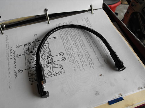
As far as other random stuff, my keyboard light showed up today! It’s actually a goose-neck style light that is used on DJ / Mixer equipment and should be a nice solution to our illumination problem, more on this next week:


