
Whats up everyone?
I hope that everyone has been enjoying their summertime! Seriously if you haven’t taken the time to stop and enjoy the outdoors PLEASE DOSO!
So what have I been upto? Cleaning up and catching up on things that were neglected because of my devotion of time to Albert. I have had some time to enjoy the outdoors, I want squeeze in a camping trip sometime soon so hopefully I can work that in somewhere.
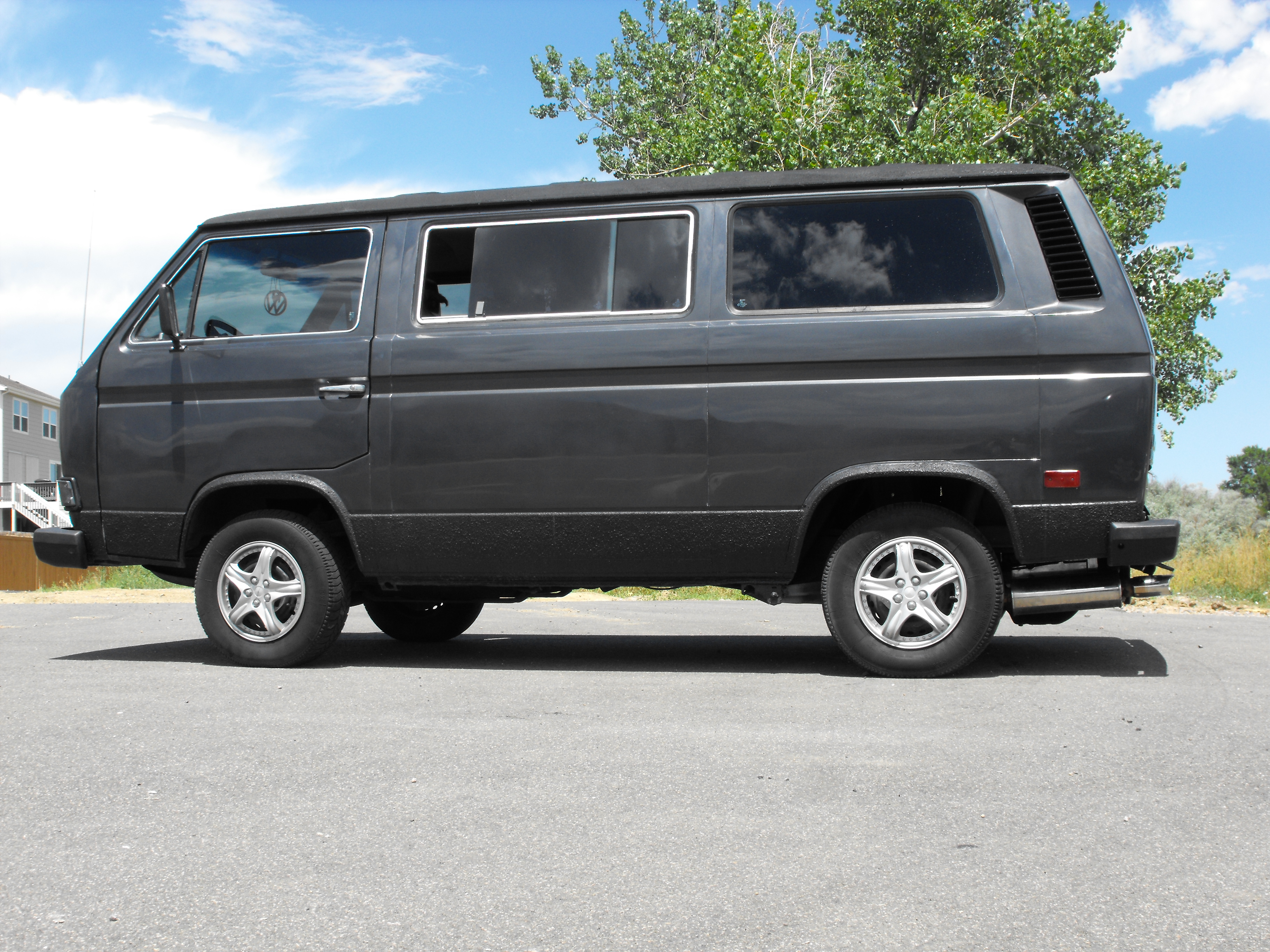
I took some more pictures of the Van, some were just out next to my house, others I decided to adventure out some more:
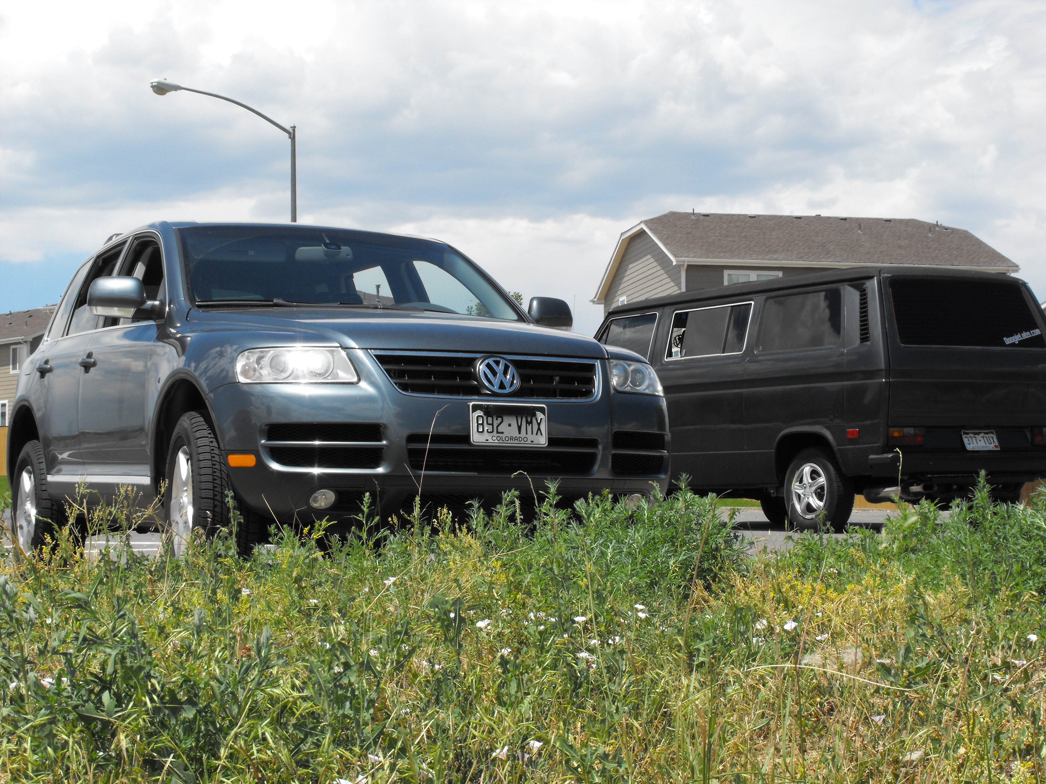
Snagged a couple of buddy’s Tourage so i’ll throw one in:
These next ones in the set were taken at the St Vrain power facility, I needed some to update the old nightshots:

I played with exposure and position and a few useable ones came out:


These sides shot came out freaking sweet!

Above and below are definitely two of my most favorites!

After that we snuck over to Boulder for a couple of cool night shots, only these two came out the rest were pretty fuzzy:

This is probably my favorite out of the boulder ones:

LED Keyboard Light:
Let’s face it, the Vanagon has what I would call “substandard” lighting, they give you three skimpy sized dome-lights that could be called mood-lighting at best. Even at that, they only give the driver one up front and the passenger is left asking the driver to turn on a distraction over their head so the passenger can see what they are doing. Having a carputer in Albert has compounded this problem, because when passengers want to jump to a favorite song at night it can be a cumbersome task even with the factory lighting.
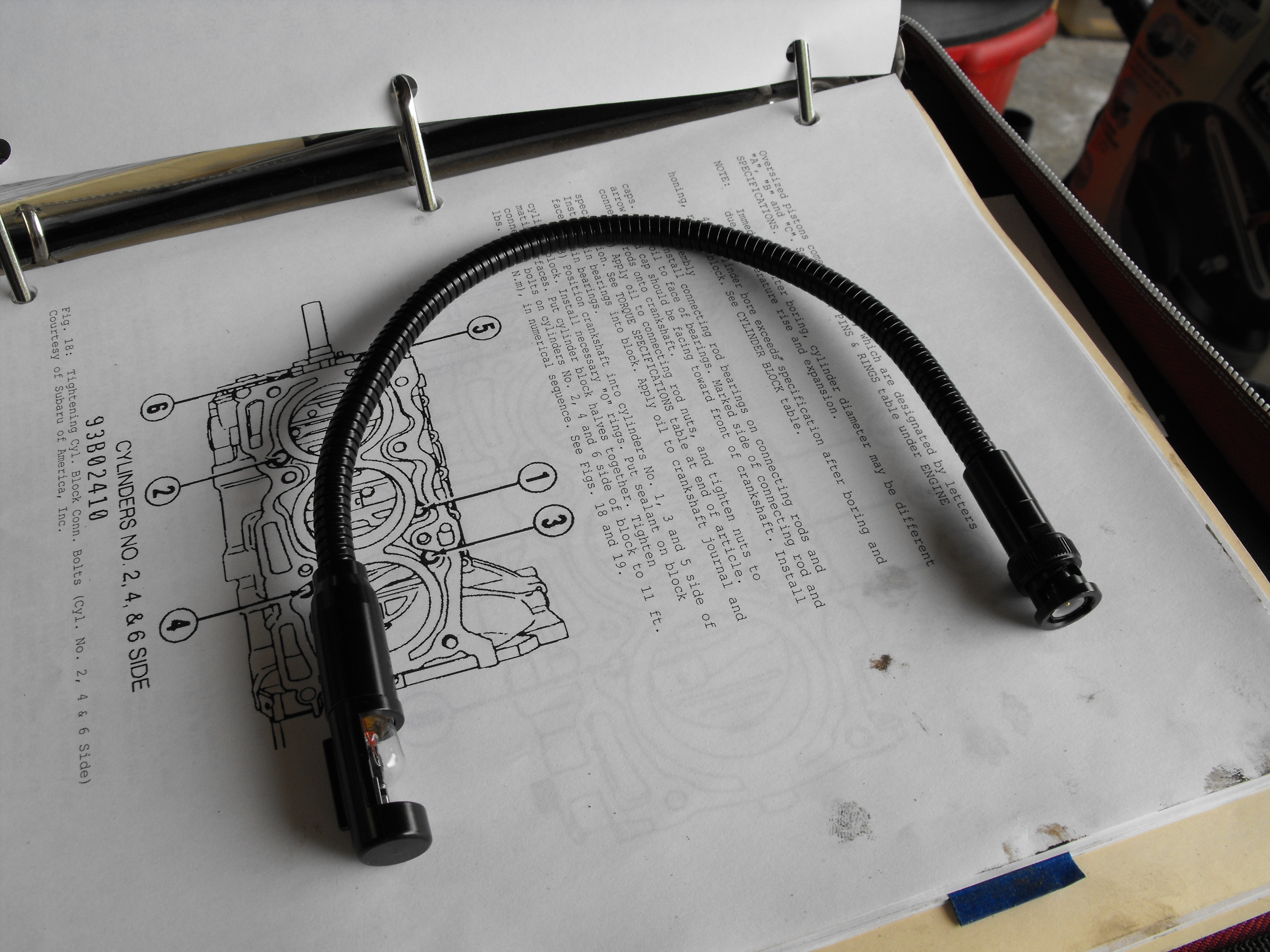
So I set out hunting for a solution, I decided I wanted a re-positionable light because not everything the passenger does involves the keyboard, I also wanted it dimable because a soft direct light over the keyboard is really all that is needed and isn’t distracting, whereas other times we need a spotlight. After browsing on eBay I came across the Gooseneck style flexible lamps used in mixers, tables, etc for pro audio. They use a BNC style connector to plug into the panel which is sturdy and easily sourced, and the best part is it’s removable! It comes with a 5 watt incandescent style light bulb which was plenty for the keyboard, but seemed lacking in the other use department. Knowing I needed a different bulb I went ahead and purchased the light and a short time later this is what showed up at my door:
It uses a bulb with a socket similar to 1156 or 1157 automotive bulbs but smaller, a T4W or H6W would be a great comparison to the stock lamp size. So I disassembled the light and removed the bulb, then I broke the bump out and desoldered the remaining glass leaving me only the base. The enters the LED’s chosen for this project:

These are surplus gaming machine parts like the games used in casinos. These most likely illuminated a button or a sign, they contain 3 white LED’s and no resistors. I am unsure of the light output or power requirements:
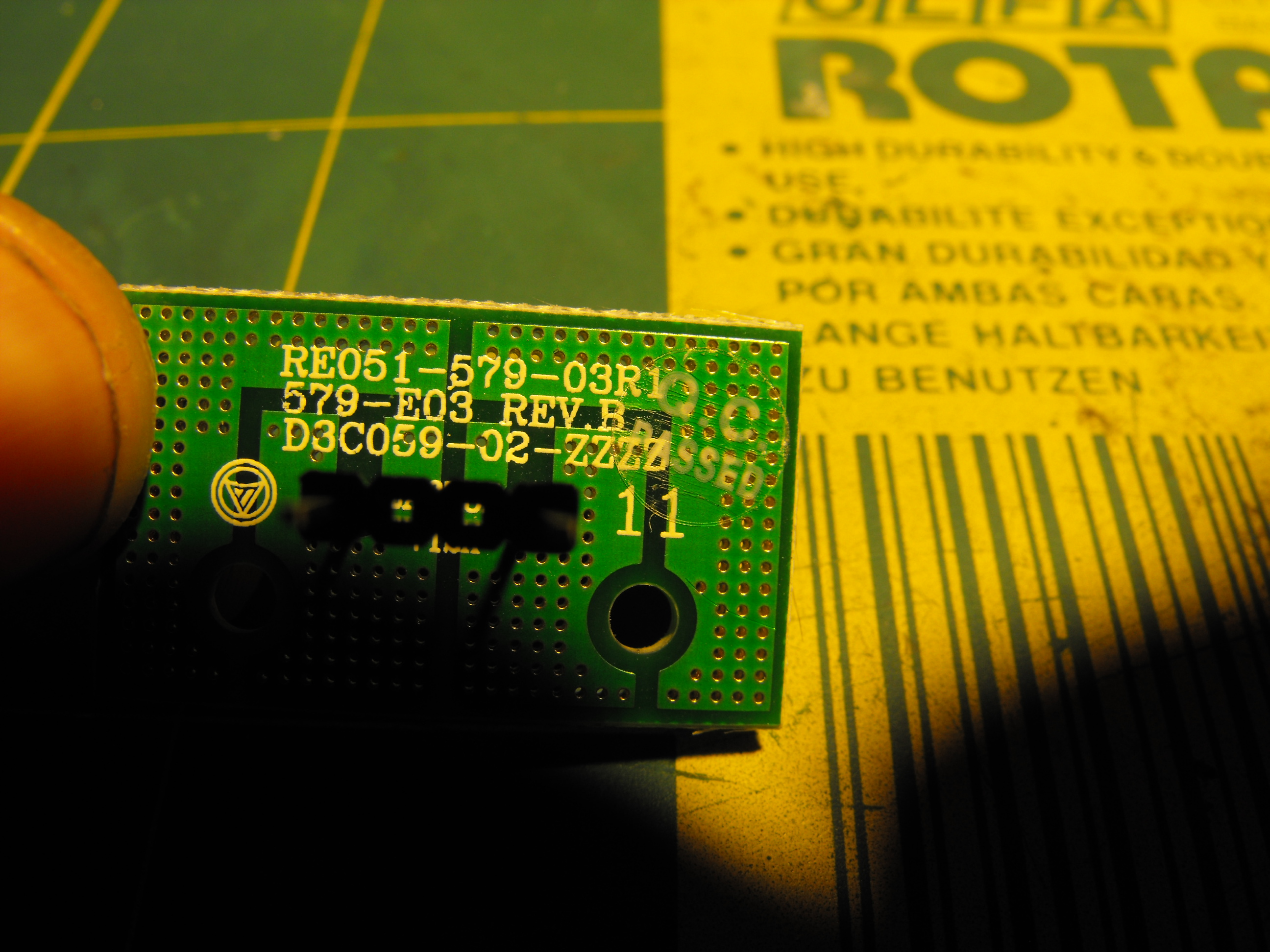
Next using a heat gun I heated up and de-soldered the LEDs from their original board. Leaving the bare board behind:

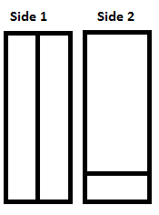
Next I took my empty bulb base and cut a small piece of PCB stock 3/8 – 1/2″ wide and 1 3/4 – 2″ long. You will need to be concerned about the total length so it fits in your fixture and you’ll want the width to be skinny enough that one side doesn’t touch the side of the bulb base. Then you’ll need to etch or score a line down the center of one side the full legth of the pcb. This splits each half of the board into positive or negative:

Next you’ll want to score a line on the backside so that 1/4″ to 3/8″ of the bottom is divided off. It should look like the picture below:
Since the LED’s were pointing down on the PCB and my PCB material is double sided it left me ample room above the board for the resistor. I chose a 1/2 watt resistor and wired all 6 LED’s in parallel. It should be known that it’s actually not good by design to wire LED’s in a parallel fashion, when using a few with one resistor they should be wire in series. Since these were free I decided to overlook it for this exercise, here is my resistor setup:
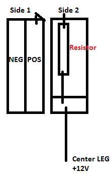
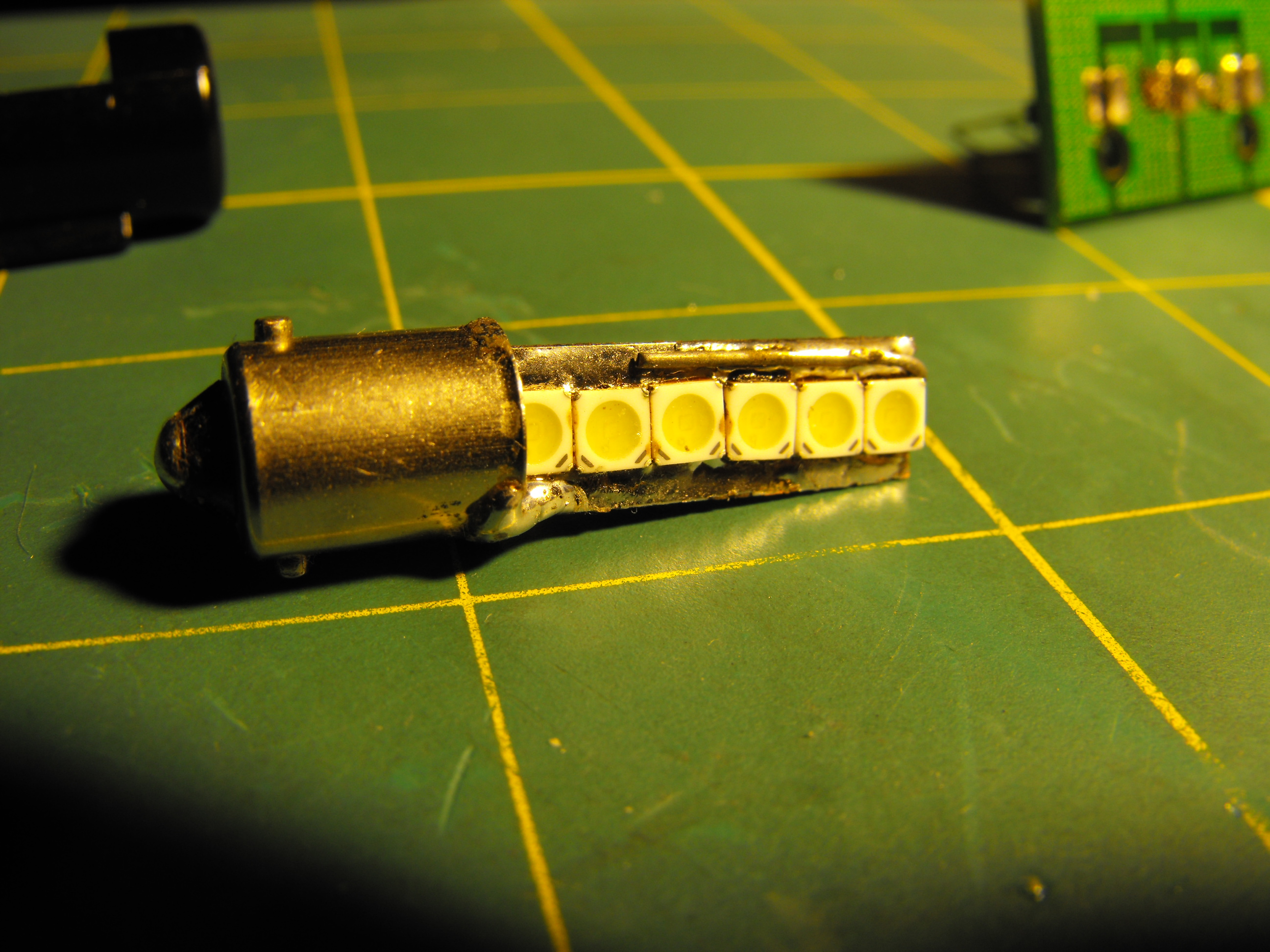
The “Center LEG” is just a piece of wire that stick through the very end of the bulb base, when mating the two together you solder the leg at the bulb tip and then cut the excess off, this becomes your bottom contact point. After I got the resistor mounted I decided to give things a test fit to see how we were looking:

In this picture you can see a good example of how I looped one end of the resistor over to make contact with the opposite side of the board:

To solder the LED’s I tinned them with a regular fine tipped soldering iron and then lined them up flat on the board and heated them up with a heat gun to stick them to the board, if you don’t have a pair of alligator claws to hold your workpiece in place it may be easiest to install the LED’s first and then worry about the resistor and base later. If you are surface mount soldering like I am it may help to tin the PCB with solder if you are inexperienced.
Note the small solder point on the side of the board to the bulb base. The side of the bulb base is considered negative or ground, and this is the opposite side than that of the resistor linked one:

A comparison of the newly manufactured bulb against the light fixture itself:

Here it is against my first attempted quickie “LED Bulb” the single LED is 100,000mcd brightness:

Here is the new bulb assembled into the fixure:

Here it is tested:

It’s much brighter than the 100,000mcd single LED bulb that I made, I installed this along with a POT and a SPST switch on the dash for better control and it works great! I’ll have to post some more pictures of the final installation as you don’t get the full idea unless you see it in the Van. I really like the versatility this has brought to Albert’s cabin and should make road trips a little more pleasurable.
The bug-in is next Sunday, I’ll see you there and yes, I’m racing Albert! You can most certainly expect a video out of this one! I’ll have plenty of pictures to post up so keep your eyes peeled for those. Who knows maybe I’ll win something!?
I have also updated the JDM engine page with the latest information, and is now considered completed. I hope it will be of great use to many of you in the future. I am going to focus on getting the port-work page posted this week. It’s probably not even 25% complete at this point but give me the rest of the week and I should have turned it around a bit.
I am considering a “services” page to offer up some services for some extra cash. If anyone would be interested in any type of port-work / electrical service hit me up I am open for some discussion.
Upcoming projects? Actually, I am slowly rolling into another project but the details at this point are best kept secret. It’s not really car related but it’s something you’ll definitely want.
Stay tuned
– Doogie