

After a long busy week I didn’t really get a chance to compile the latest stuff from the build that we have so far. Well, let’s kick it off. . If you haven’t seen the video for Day #2 on the computer case already, here ya go:
 For this fan there are 6 wires, here is the wiring diagram / pin-outs that I have sourced from the interweb: Black = Ground Orange = open-collector tachometer Red = +12 VDC Yellow = open-collector, low-pass/high-fail, trip-point (speed) and locked rotor alarm Blue = Ground Green = pulse-width modulated speed control There is actually a short video I took on these fans not to long ago when I needed something to test my new Li-Po battery packs for the quadrotor helicopter that I am building. You don’t really get an idea of the CFM, but it’s a funny video anyways:
 So with it mounted in the case, at a beefy 51mm thick, there is just enough room on each side for the condenser coils and the plumbing to run up and down. I need to find a good place to source material to create new capillary tubes, since the given size of my “evaporators” are going to be different, and I’m going to be running a couple different evaps I will need to make more than one capillary tube. Lots of planning and math is going to need to go into this for a sure fit. On Day #3 I covered fitting the power supply to the front of the case . .
 It’s basically an offset 120MM fan hole, and I will use the fan mounting screws built into the power supply to mount it to the case. This is for both simplicity, and incase I need to use a different PSU later I can mod the new PSU with a 120mm fan or locate it in a different place altogether and I’m not left with a weird hole to deal with. I used a right angle IEC cable I had found as well, and will notch the motherboard tray so I can run it up the far side front of the case and far away from any other cables for the best EMI shielding that’s possible. I don’t suspect there will be any issues, but it’s good to be prepared. I also took measurements of the case window, and will order the stuff I need from Mnpctech. There is a new window kit coming out soon that will work perfect for this application, and it’s going to be totally awesome with this case, we definitely are going to want to peer inside on this one.
  I also found these Diamond Knurl Case Feet that I already have the holes for and would compliment the build perfectly, I think I am going to pick up a set of those as well! (Clicking image will take you to product page so you can snag a snazzy set for your project!)
 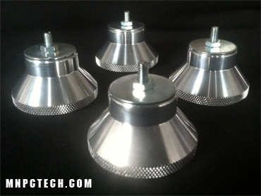 I will also be picking up an old boiler sight glass like the one below. This will go on the suction line after the evaporator blocks, this is not only for aesthetics but also to monitor the load of the refrigeration loop and ensure that no liquid is being returned back to the compressor. Mounting it in a fixture that doesn’t leak refrigerant might end up being a challenge though 🙂 (click pic for eBay link)
 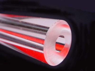 So that’s where we are at for the latest progress, some stuff is done, lots is still in planning, but we are starting to take more and more shape. Wish me the best on progress, and please keep poking in to see what comes of it. Coming up next week we’ll do a bit more plumbing, and start to investigate more wiring details and component placement. I will be giving Mike, our machine shop guy, the front case panel this week to hopefully cut out a special logo into the front as a fan grill. Check out the additional pictures below from the build so far. I also included some shots of the motherboard.


Stay tuned for more awesome!