9/28 Update:
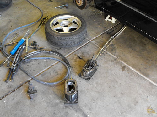
Got more done on the Corrado, decided I should share what I have. Installing the Frankenstein shift-box and cables into the car:
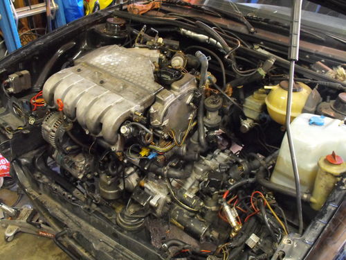
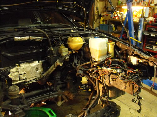
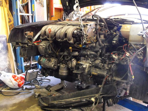
More hooking up stuff:
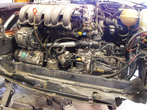
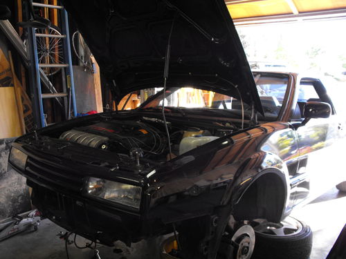
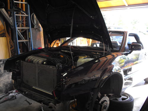
Looks good up front, aluminum crack pipe as well as a low temp thermostat:
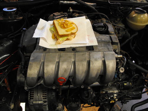
I built a great sandwich holder:
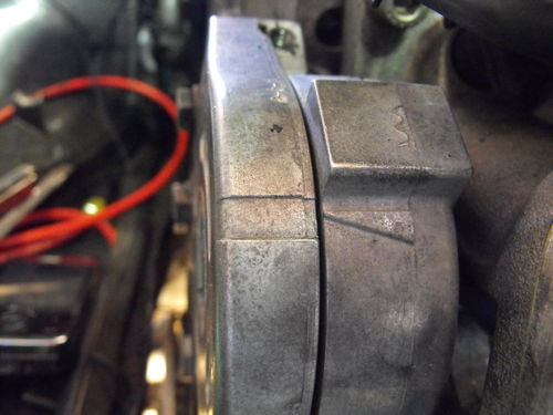
Discovered that VR6s have a built in belt stretch indicator today too, that was pretty cool!
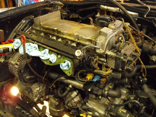
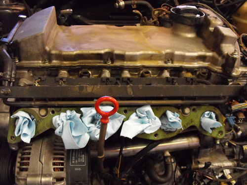
Removed the intake manifold for a good cleaning, and well intake manifold exchange:
It was a bit messy down there!
That was about the point I had to goto work, so tonight I have lots more todo!
Enjoy 😀
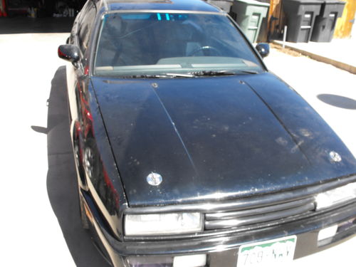
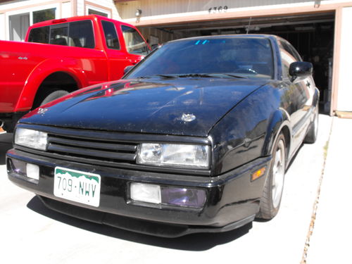
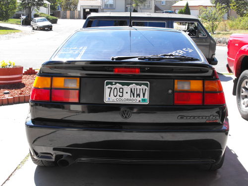
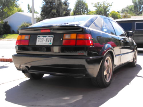
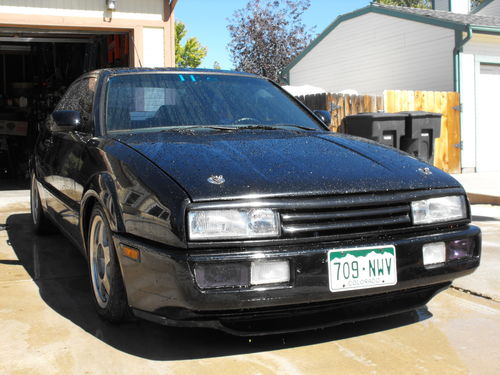
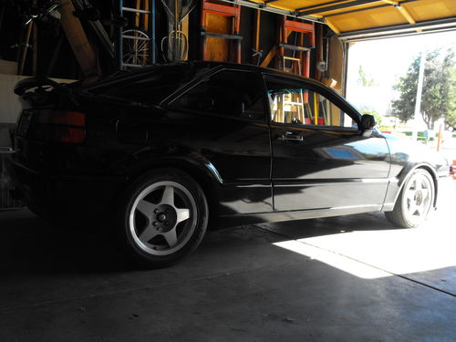
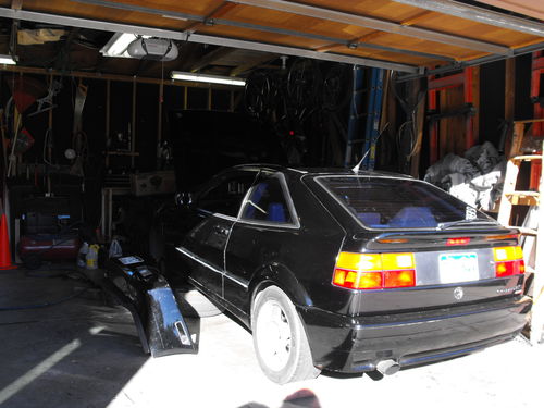
The Corrado is home!
I am fixing it up so I can drive it to wherever I move or if I need a spare car on the weekends. This is temporary as the engine building gets started this winter:
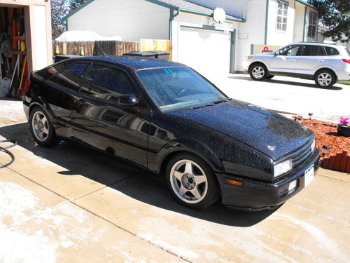
Her first bath in 2 very dusty years, cleaned up really nice!
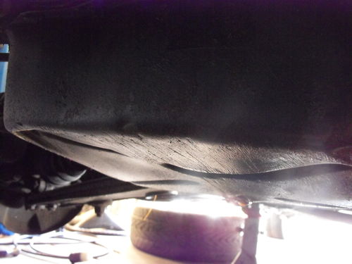
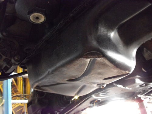
The oil pan was completely messed up, I am surprised the engine even had decent oil pressure!
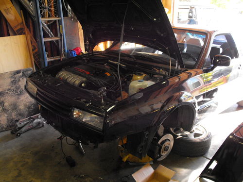
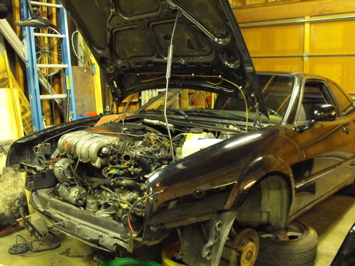
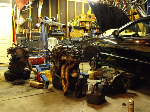
Time for the teardown to begin:
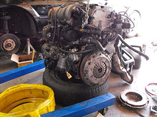
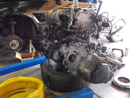
I decided to purchase a new engine for this car to be installed with the new transmission. The old engine runs great but uses oil and it smells it and burns it a little bit. The old engine will become the core for the 750+ HP Monster this car will become:
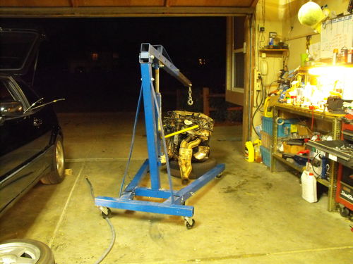
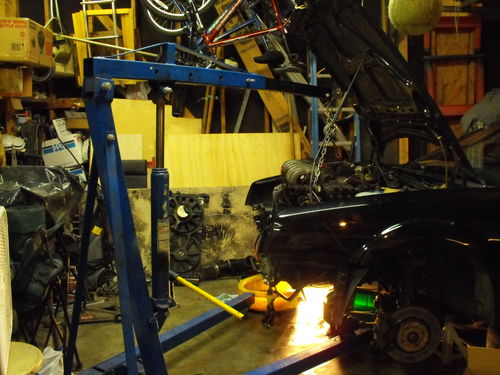
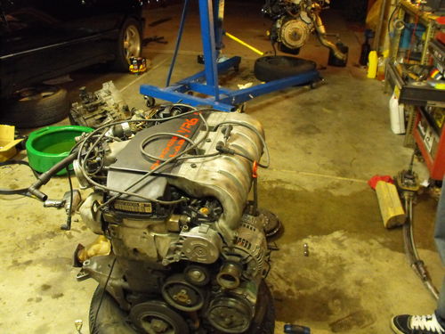
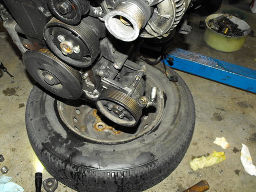
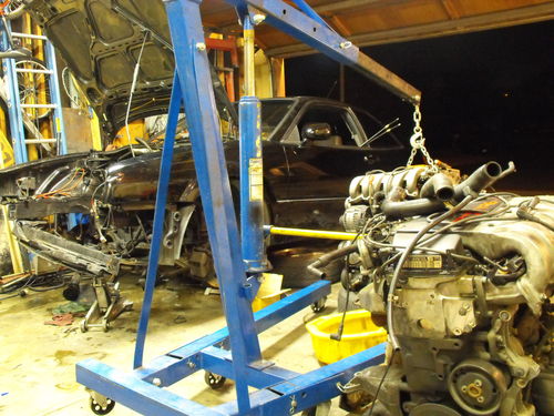
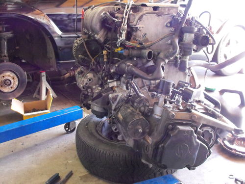
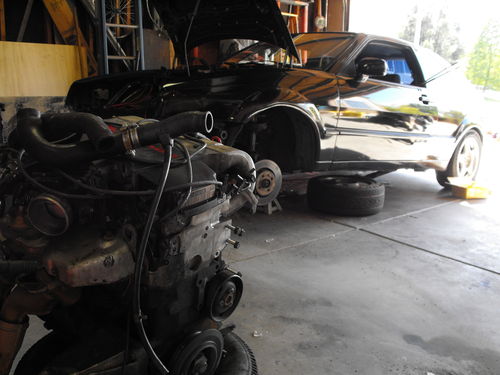
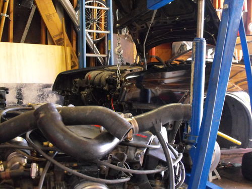
Now that the new engine was delivered it was time to finish removing the old one:
All in all that was not bad!
Since my G60 is now a VR6 I run into an issue just like most do with the power steering system.. For those who don’t know the VR6 and the G60 take different types of power steering fluid that they aren’t very compatible with each other. Up until now I picked the route of destroying the power steering pump instead of the G60 rack so I always ran regular power steering fluid. The pump had been annoyingly loud ever since the swap was first done. Tonight I took an extra special look into the power steering pumps between the G60 and the VR6, and came up with the process for installing the G60 pump onto a VR..
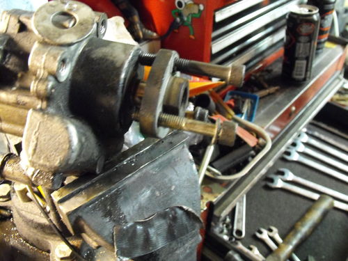
As it turns out, the pump actually bolts into the VR bracket without any modification, the difference here is the drive flange that is pressed on to the pump’s shaft. If you look at the G60 one it poitions the pulley and inch or more out than it does on the VR. This of course causes belt alignment issues so most people would just say at that point that you cannot use the pump. Actually, you can swap the ends!
I started by using bolts to walk the VR6 one off of its shaft, if you use this method remember to use washers or another flat piece of metal to push against. Using the housing could cause it to crack:
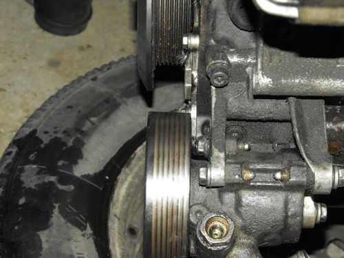
VR6 center and pulley installed on pump:
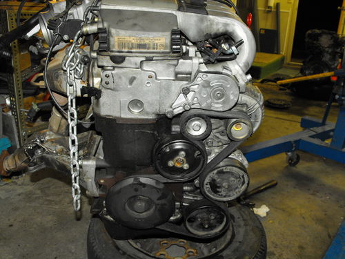
Belts are done:
Pretty much where I left off for the night:
Then I got some time this morning while on Lunch from work, so I was able to make more progress:
Got the garage cleaned up and the tools put back away:
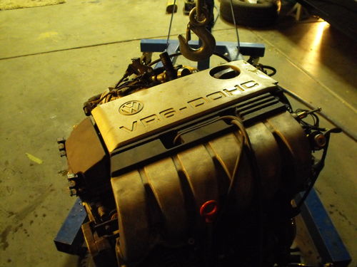
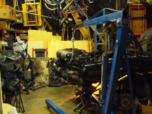
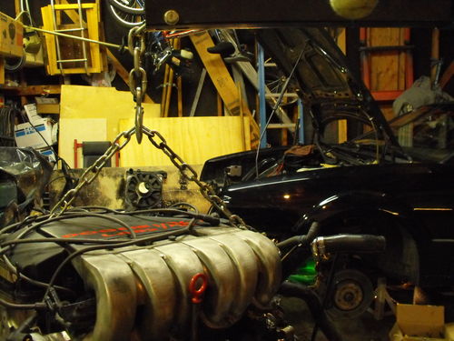
New engine / trans assembly is dangling back in the engine bay ready for installation:
Just need to switch the intake manifold with my own:
I need to change the shiftbox and cables and then I’ll be ready for actual engine installation. This should be done very very soon.
My Phone has pretty much bit the Dust! The partying over the weekend took its toll, I was pretty trashed at the bar, double fisting jack and cokes while texting at the same time. I spilled jack and coke all over the phone and then dropped the phone on the floor which promptly caused it to explode into 3 separate pieces. In the midst of my intoxicated arse trying to pick everything back up I managed to drop the battery again and cracked the side of it. My uber 3000MAh Mugen Battery no longer holds a charge 🙁
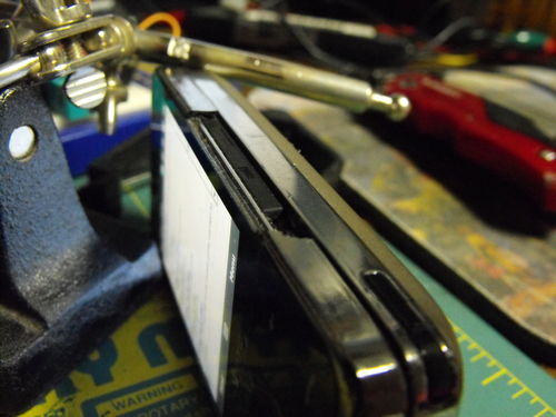
Now it’s back to using a phone that I have to charge twice a day 🙁 It’s been almost a year that I have had this phone which makes this the longest surviving PDA phone I have had. The bezel around the screen was cracking and a piece fell off while in my pocket exposing the side of the screen and digitizer glass:
I will be ordering a parts phone this weekend, I have been looking for something that’s in decent shape but has bad main board. Hopefully I can come up with something, everyone has pretty much moved on to the trouchpro2 so there isn’t much left around for these older phones. The plan is to have this phone hold me over until the iPhone comes out for CDMA. I am willing to pay the $500 for it without a contact and I want to attempt to be the first to flash it to Cricket.
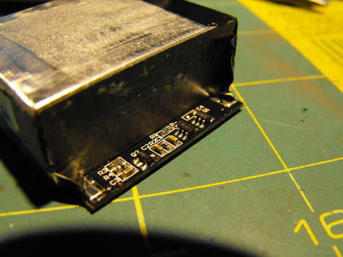
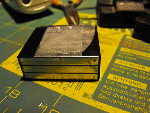
After taking a closer look at the battery I couldn’t get it to work that night, so my drunkifiedness disassembled the pack. There are 3x 1000MAh cells in here. Its interesting how these cell batts are fairly standardized as far as size so it appears that you can actually construct your own packs providing you are competent and comfortable building a charging circuit for it. I have been collecting good phone batteries to snag the li-ion cells out of for a quad rotor helicopter project I will be starting eventually.
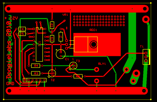
I have also been working on the Cascading coolers project, I made up a circuit board that actually controls the two coolers using a N channel Mosfet. This allows me to program for optimum efficiency over various conditions. I stole 2 temp sensors of an old motherboard I had laying around and incorporated them into this design for both feedback and safety. Using the Express PCB software I came up with this design:
There isn’t too much to the circuit, the parts list is as follows:
IC1: Pic16f628A
REG1: LM317T
R1: 240OHM
C1: 1uF Electrolytic
C2 – C5: .1UF Ceramic
VR1: 20K Surface mount POT (needs to be 5k really)
T1: IRF3205
T2 & T2: 2N4403 PNP
RLY1 – 12Volt 5A Relay
I decided to go with the 317T so I could set the voltage at 6v or whatever I wanted really. I figured at one point I’ll probably raise the input voltage to somewhere around 15 so its best to have this adjustable.
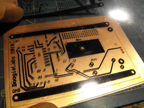
Satisfied with my board design I decided to move forward with making it into an actual board, since I have a bunch of overhead transparencies I decided to use them to drill the board alignment holes and do one last final check on the design. I think I will keep these transparencies in a folder too, would make a great collection of every board I have designed:
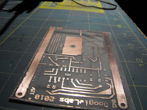
So a short time later I ended up with this:
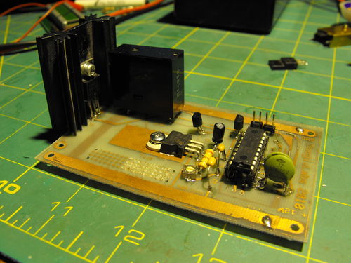
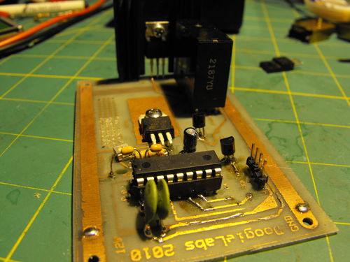
Board assembly went rather smooth, well, smoother than it was drilling all the tiny little holes when the chuck lets go dragging a razor sharp drill bit across my fingers slicing them open.
Like I said there really isn’t much to it, I just really wish this worked good enough to allow me surface mount components with lots of pins. At least for these heavier current applications I can use this method with good success.
After doing some preliminary testing it looks like the transistor I had chosen isn’t enough to drive this relay so I am going to have to do some minor modification to this circuit.

